Table of Contents
Advertisement
Advertisement
Table of Contents

Related Manuals for karmek one ALICE CANALIZZATA

Summary of Contents for karmek one ALICE CANALIZZATA
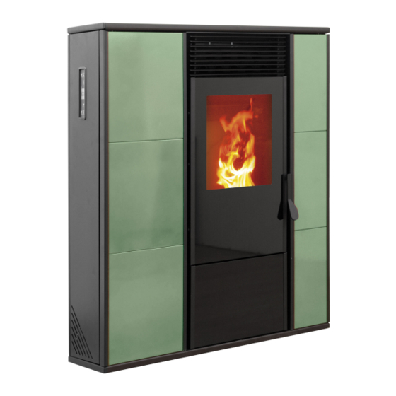
- Page 1 CHANNELED PELLET STOVE ALICE CANALIZZATA OPERATING AND MAINTENANCE HANDBOOK...
- Page 2 Karmek One S.R.L. PLEASE NOTE: Karmek One reserves itself to carry out unsubstantial changes to the stove’s components, which may not be reported in the present handbook, those being of small entity. Occasional appearance changes from the flyers are due to ordinary seasonal updates.
- Page 3 A. GENERAL INFORMATION a.1 General safety rules a.2 Technical features a.3 Accessory equipment a.4 Identity plate a.5 Guarantee a.6 Suitable fuel a.7 Ordering spares B. INSTALLATION INSTRUCTIONS b.1 Initial warnings b.2 Moving and transporting b.3 Positioning b.4 Channeling b.5 Installing the flue gas outlet b.6 Installing the combustion air inlet pipe b.7 Connecting to the power supply C.
- Page 4 D. FUNCTIONS OF THE MECHANICAL AND ELECTRIC COMPONENTS d.1 Screw motor d.2 Smoke intake motor d.3 Tangential fan d.4 Centrifugal fan d.5 Electronic card d.6 General switch d.7 Fumes probe d.8 Room probe d.9 Sparking plug d.10 Thermocouple E. ORDINARY CLEANING AND MAINTENANCE e.1 Cleaning and maintenance by the customer e.2 Periodic maintenance by the Assistance Center F.
-
Page 5: General Information
A. GENERAL INFORMATION a.1 General safety rules ATTENTION PLEASE!!! You can never be too cautious: before the installation read and comply with these fundamental Rules: ● All local regulations, including those referring to national and European laws, must be respected while installing the stove. ●... - Page 6 If anomalies in the functioning should occur, light the stove again only after fixing the problem at its origin. ● Karmek One Srl is not responsible for inconveniences, tampering, breakages or any other damage due to non-observance of the instructions reported in this handbook. ●...
-
Page 7: Technical Features
mental abilities or low experience and knowledge, unless they have been supervised or educated to the use of the appliance by the person who is responsible for its security. a.2 Technical features Nominal power: 12Kw Average efficiency: Heating capacity: 280-310m³ Power supply: 230V 50Hz Nominal power absorption:... - Page 8 1 Side fumes outlet 2 Top fumes outlet 3 Rear fumes outlet 4 Combustion air inlet 5 Switch and power socket 6 Channeled air outlet...
-
Page 9: Suitable Fuel
Guarantee The guarantee certificate, which we consigned to you when you purchased the stove, must be sent to the producer firm Karmek One Srl, 8 days after delivery date the latest; otherwise, the guarantee itself will no longer be valid. -
Page 10: Installation Instructions
B. INSTALLATION INSTRUCTIONS b.1 Initial warnings The device must be installed on a pavement that presents an adequate burden capacity. If the existing building does not satisfy this requirement, appropriate measures (for instance a burden distribution plate) must be taken. The installation of the device must guarantee an easy access to clean the stove, the exhausted gas piping and the flue. - Page 11 The information reported above is purely indicative for a correct installation; Karmek One Srl is not responsible for what concerns the installation.
-
Page 13: Connecting To The Power Supply
b.6 Installing the combustion air inlet pipe For any described solution, two alternatives are possible: ● Draw the air directly from the outside through a piping (internal Ø 50mm; max length 1,5m), connected to the air inlet pipe on the back of the stove. ●... - Page 14 ELECTRICAL SCHEME...
- Page 15 C. OPERATING INSTRUCTIONS c.1 Initial warnings All regulations, included those referring to national and European laws, must be respected when installing the device. Do not use the device as an incinerator or in any other way than that for which it was designed.
- Page 16 C.3 User menu Press the P3 key (MENU) to access the menu. The menu has various voices and levels that allow access to the settings and to the programming of the stove. Each level is reached by selecting an item and pressing the P3 key. To go through the items list use the P1 and 2 or 5 and 6 keys.
- Page 17 05 - tuesday prog 1 on/off 06 - wednesday prog 1 on/off 07 - thursday pog 1 on/off 08 - friday prog 1 on/off 09 - saturday prog 1 on/off 10 - sunday prog 1 on/off 11 - start prog 2 time 12 - stop prog 2 time...
- Page 18 05 - stop 2 04 - select language 01 - italiano 02 - francais 03 - english 04 - deutsch on/off 05 - mode stand-by 06 - buzzer on/off 07 - load initial 08 - state stove C.4 Adjust blowers Allows the adjustment of the two fans independently.
-
Page 19: Set Clock
C.5 Set clock Sets current time and date. The motherboard clock is fitted with a lithium battery that grants 3/5 years of operating time. C.6 Set chrono - enable chrono Switches on or off all chronothermostat functions. - program day Enables, disables and sets daily chronothermostat functions. - Page 20 selezione significato valori possibili START 1 ora di attivazione ora - OFF STOP 1 ora di disattivazione ora - OFF START 2 ora di attivazione ora - OFF STOP 2 ora di disattivazione ora - OFF - program week Enables, disables and sets weekly chronothermostat functions. The weekly programmer features 4 independent adjustable programs.
- Page 21 Program 2 menu level selection meaning allowed values 03-03-11 START PROG 2 lighting time time - OFF 03-03-12 STOP PROG 2 switching off time time - OFF 03-03-13 MONDAY PROG 2 on/off 03-03-14 TUESDAY PROG 2 on/off 03-03-15 WEDNESDAY PROG 2 on/off 03-03-16 THURSDAY PROG 2...
- Page 22 - program week-end Enables, disables and sets chronothermostat functions for the week-end (saturday and sunday, days 5 and 6). TIP: The programming function features fairly elaborate procedures. It is advisable to activate one weekly program at a time. Avoid enabling daily, weekly and week-end programs at the same time, choose the one that mostly fits your planning and disable the others.
- Page 23 C.10 - load initial This mode, that should be used only before lighting and with the stove cooled down, allows to charge the grate with pellet for 90”. Start charging with P1 key and stop with P4. C.11 - state stove Displays the state of the stove reporting information about the various devices connected.
- Page 24 C.12 Failed lighting If the time set in Pr01 is exceeded and fumes temperature did not reach the minimum allowed value set in Pr13 with a rate of 2°VC/min, the stove goes into an alarm state. C.13 Working phase Once lighting phase ends correctly, the stove enters working mode, that is the normal operating condition of the stove.
- Page 25 D. FUNCTIONS OF THE MECHANICAL AND ELECTRIC COMPONENTS d.1 Screw motor The screw motor drives the screw, which brings the pellets from the tank to the grate. d.2 Smoke intake motor The smoke intake motor is fixed on the extraction turbine on the back of the stove.
-
Page 26: Sparking Plug
d.6 General switch This electronic component of the stove is composed by a 4A fuse and by an electronic filter that protect stove from electrical overload electromagnetic inconveniencies. d.7 Fumes probe The fumes probe surveys the fumes’ temperature in the intake turbine, and it operates when the temperature reaches 270°C, driving the stove to the conservation mode “RIS”... - Page 27 E. ORDINARY CLEANING AND MAINTENANCE e.1 Cleaning and maintenance by the costumer Before lighting the stove, it is advisable to clean the inside of the stove. ● Open the door and vacuum the fire table. ● Remove the great, verify its cleanliness and clean the holes if necessary. ●...
- Page 28 F. ALARMS DISPLAYING If a malfunction occurs the motherboard signals the problem and performs different actions based on the type of the alarm. The following table lists all possible alarms and the condition or device that causes each one. Alarm origin Message displayed Fumes probe ALARM SOND FUMI...
- Page 29 F.4 Alarm for absence of fire while in working phase This alarm is activated if during working phase the fire goes off and fumes temperature falls below the minimum treshold set in Pr13 parameter. F.5 Alarm caused by failure of the fumes motor This alarmi ensues when the smoke intake motor fails.
- Page 30 G. SOLUTION TO POSSIBLE PROBLEMS PROBLEM POSSIBLE CAUSE SOLUTIONS Lack of power. Check if the power supply cable is connected. The display is blank and the keys do not work. Anomalies in the connection Check if the display and the card between the display and the card.
- Page 31 PROBLEM POSSIBLE CAUSE SOLUTIONS IMPORTANT: unplug the stove before ridding the screw of The stove is blocked for possible obstructions Technical problem with the screw. an unsuccessful pellet ridding the chute of supply. possible obstructions removing the pellet dust accumulation from the bottom of the tank.
-
Page 32: Guarantee Conditions
0438 1883101 fax 0438 1883103 info@karmek.it e-mail GUARANTEE CONDITIONS: AT THE END OF EACH SEASON, IT IS OBLIGATORY TO HAVE THE AUTHORIZED ASSISTANCE CENTER PERFORM GENERAL CLEANING OF THE STOVE; OTHERWISE, THE GUARANTEE WILL EXPIRE. ALICE CANALIZZATA HANDBOOK – REV. 00 310513...
Need help?
Do you have a question about the ALICE CANALIZZATA and is the answer not in the manual?
Questions and answers