Philips MCD703 Service Manual
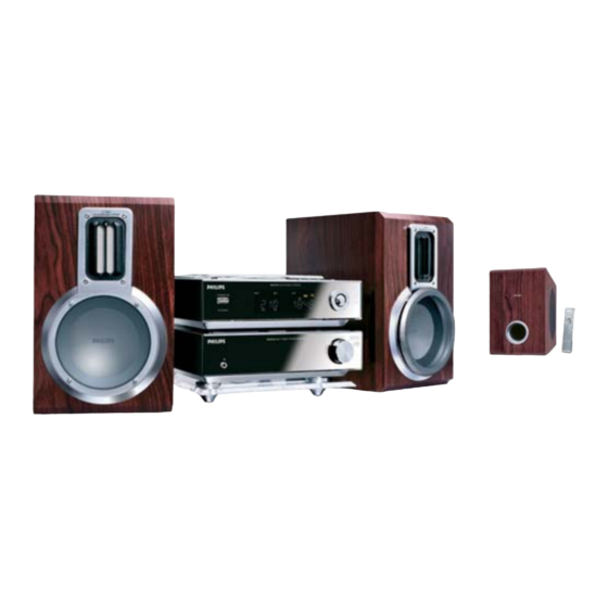
Dvd micro system
Hide thumbs
Also See for MCD703:
- User manual (39 pages) ,
- Owner's manual (38 pages) ,
- Service manual (33 pages)
Table of Contents
Advertisement
DVD Micro System
Service Manual
TABLE OF CONTENTS
Handling chip components ............................................................1-1
Information about lead-free soldering ............................................1-2
Technical specification...................................................................2-1
Service tools ..................................................................................2-1
Service measurement setup ..........................................................2-2
Connections and controls ......................................................3-1...3-3
Troubleshooting.....................................................................3-4...3-5
Disassembly diagram ............................................................4-1...4-2
Software version and upgrading ....................................................5-1
Set block diagram ..........................................................................5-2
Set wiring diagram .........................................................................5-3
VFD / KEY BOARD ASSEMBLY
circuit diagram ..........................................................................6-1
layout diagram ..........................................................................6-2
©
Copyright 2006 Philips Consumer Electronics B.V. Eindhoven, The Netherlands
All rights reserved. No part of this publication may be reproduced, stored in a retrieval
system or transmitted, in any form or by any means, electronic, mechanical, photocopying,
or otherwise without the prior permission of Philips.
Published by LX 0609 Service Audio
Version 1.0
Printed in The Netherlands
Subject to modification
TUNER BOARD
circuit diagram ..........................................................................7-1
layout diagram ..........................................................................7-2
DVD BLOCK
circuit diagram ..........................................................................8-1
layout diagram ..........................................................................8-2
AMP BLOCK
circuit diagram ..........................................................................9-1
layout diagram ..........................................................................9-2
DVD MPEG BOARD
circuit diagram ..............................................................10-1...10-5
layout diagram ........................................................................10-6
Exploded view diagram................................................................11-1
Mechanical partslist .....................................................................11-2
Electrical partslist...............................................................12-1...12-3
LASER PRODUCT
MCD703
all versions
CLASS 1
© 3141 785 30930
Advertisement
Table of Contents

Subscribe to Our Youtube Channel
Related Manuals for Philips MCD703


Summary of Contents for Philips MCD703
-
Page 1: Table Of Contents
LASER PRODUCT © Copyright 2006 Philips Consumer Electronics B.V. Eindhoven, The Netherlands All rights reserved. No part of this publication may be reproduced, stored in a retrieval system or transmitted, in any form or by any means, electronic, mechanical, photocopying, or otherwise without the prior permission of Philips. -
Page 2: Handling Chip Components
1 - 1 HANDLING CHIP COMPONENTS... -
Page 3: Information About Lead-Free Soldering
To avoid wear-out of tips switch off un-used equipment, or reduce heat. • Mix of lead-free solder alloy / parts with leaded solder alloy / parts is possible but PHILIPS recommends strongly to avoid mixed solder alloy types (leaded and lead-free). -
Page 4: Service Tools
4 Hz - 22 kHz (48kHz) Weight : 1.4 Kg 4 Hz - 44 kHz (96kHz) DVD Part AMP Part : 3.1 Kg Digital Output : SPDIF (Sony Philips digital interface) Coaxial No. of programmable tracks : 20 Signal-to-noise ratio : 50 dBA AMPLIFIER... -
Page 5: Service Measurement Setup
2 - 2 SERVICE MEASUREMENT Bandpass Tuner SW LF Voltmeter 250Hz-15kHz Aerial replacement e.g. PM2534 e.g. 7122 707 48001 RF Generator Capacitor e.g. PM5326 S/N and distortion meter e.g. Sound Technology ST1700B To avoid atmospheric interference all AM-measurements have to be carried out in a Faraday«s cage. Use a bandpass filter (or at least a high pass filter with 250Hz) to eliminate hum (50Hz, 100Hz). -
Page 6: Connections And Controls
3 - 1 CONNECTION AND CONTROLS... - Page 7 3 - 2 CONNECTION AND CONTROLS...
- Page 8 3 - 3 CONNECTION AND CONTROLS English...
-
Page 9: Troubleshooting
3 - 4 TROUBLESHOOTING... - Page 10 3 - 5 TROUBLESHOOTING...
- Page 11 4 - 1 4 - 1 DISASSEMBLY INSTRUCTION - DVD PART A. Remove Bottom Cover C. Remove Side Panel (L & R) E. Remove Front Cabinet A1 remove screws M2.5x4 (washer head) - 4 pcs. C1 Slide out the Side Panels. E1 remove screws MK3x10 - 2 pcs.
- Page 12 4 - 2 4 - 2 DISASSEMBLY INSTRUCTION - AMP PART A. Remove Bottom Cover C. Remove Side Panel (L & R) E. Remove Front Cabinet A1 remove screws M2.5x4 (washer head) - 4 pcs. C1 Slide out the Side Panels. E1 remove screws MK3x10 - 2 pcs.
-
Page 13: Software Version And Upgrading
5 - 1 5 - 1 SOFTWARE VERSION AND UPGRADING... -
Page 14: Set Block Diagram
5 - 2 5 - 2 SET BLOCK DIAGRAM... -
Page 15: Set Wiring Diagram
5 - 3 5 - 3 SET WIRING DIAGRAM... -
Page 16: Circuit Diagram
6 - 1 6 - 1 CIRCUIT DIAGRAM - VFD / KEY BOARD ASSEMBLY VFD701 MCD-7 R703 CN701 NE-1300CD-3. G 2.2/0. 5 -24V MCD-14 2.0/3P CN1401 KEY1-1 KEY2-1 KEY3-1 R704 KEY4-1 15/0. 5 KS2-1 2.0/5P SW706 C704 CN1501 KS3-2 SW1501 KEY4-2 KEY4-2 KEY3-2... -
Page 17: Layout Diagram
6 - 2 6 - 2 LAYOUT DIAGRAM - VFD / KEY BOARD ASSEMBLY... -
Page 18: Circuit Diagram
7 - 1 7 - 1 CIRCUIT DIAGRAM - TUNER BOARD ANT 1 C3 4 R3 0 0.22u F C4 2 C4 4 R1 1 C4 1 C3 5 0.33u F 6T 5 C3 0 5T 5 C3 3 C2 9 6T 5 C1 0 C1 6... -
Page 19: Layout Diagram
7 - 2 7 - 2 LAYOUT DIAGRAM - TUNER BOARD... - Page 20 8 - 1 8 - 1 CIRCUIT DIAGRAM - DVD BLOCK CN903 JACK 901 CN806 CN809 M CD700-8 S-VI DEO JACK 902 Q807 8550 R804 STB3 C880 Q802 8550 C881 R859 100UF C807 RCA3P R840 C804 220uF 104P Q806 Q801 8050 9014 R860...
-
Page 21: Layout Diagram
8 - 2 8 - 2 LAYOUT DIAGRAM - DVD BLOCK... - Page 22 9 - 1 9 - 1 CIRCUIT DIAGRAM - AMP BLOCK R150 AUX1-L U105 TDA7264 AUX1-R R151 R153 R152 MCD-1 TDA7264 D108 R156 J103 R154 4001 R157 RCA-407 AUX2-L D109 AUX2-R 4001 R155 CD-R C107 TU-R 47uF ~12.5V CD-L ~12.5V R120 330 1/4W C176...
-
Page 23: Layout Diagram
9 - 2 9 - 2 LAYOUT DIAGRAM - AMP BLOCK... - Page 24 10 - 1 10 - 1 CIRCUIT DIAGRAM - DVD MPEG BOARD MPEG board is not repaired,program for referrence only. +12V [ 1 ] +12V R110 ASPDIF -12V MIC_L [ 1 ] -12V +12V1 [ 1 ] +12V1 DV33 220pF [ 1 ] DV33 [ 1 ]...
- Page 25 10 - 2 10 - 2 CIRCUIT DIAGRAM - DVD MPEG BOARD MPEG board is not repaired,program for referrence only. Y[1..6] Y[1..6] [ 2 ] VSYNC# VSYNC# [ 2 ] HSYNC# +5VV HSYNC# [ 2 ] +5VV [ 5 ] [ 5 ] 75/DIP [ 5 ]...
-
Page 26: Circuit Diagram - Dvd Mpeg Board
10 - 3 10 - 3 CIRCUIT DIAGRAM - DVD MPEG BOARD MPEG board is not repaired,program for referrence only. SD33 SD33 DV33 CB47 CB44 CB45 CB46 CB48 CB49 CB50 + CE25 CB58 0.1uF 0.1uF 0.1uF 0.1uF 0.1uF 0.1uF 0.1uF 100uF/16V 0.1uF NO_USE... - Page 27 10 - 4 10 - 4 CIRCUIT DIAGRAM - DVD MPEG BOARD EJS89D18 MPEG board is not repaired,program for referrence only. INDEX & POWER, RESET History Date RF, SERVO & MPEG MT1389E The original released. 2003.6.15 Change CE11 from 10uF to 100uF 2003.7.17 MEMORY - SDRAM, FLASH/EEPROM Change C3 from C to 2200pF...
- Page 28 10 - 5 10 - 5 CIRCUIT DIAGRAM - DVD MPEG BOARD MPEG board is not repaired,program for referrence only. JITFO 390pF JITFN DV33 Change R4,R5,R6,R8,R12 from ik to R 74H04 R207 100k 750k AMDAT R192 PLLVDD3 DACVDD3 RFV33 ALRCK R139 CB17 + CE15...
-
Page 29: Layout Diagram
10 - 6 10 - 6 LAYOUT DIAGRAM - DVD MPEG BOARD MPEG board is not repaired,program for referrence only. -
Page 30: Exploded View Diagram
11 - 1 11 - 1 EXPLODED VIEW DIAGRAM DVD PART AMP PART 21(22) -
Page 31: Mechanical Partslist
WOOFER ASS'Y 994000002493 DVD UNIT DISPLAY LENS 994000005074 SPEAKER WIRE 2m 994000002497 POWER MULTI BOTTON 994000005075 PH BRACKET ASS'Y 994000003497 PRE1-PHILIPS REMOTE HANDSET 994000002495 SWITCH PUSH KNOB 994000002505 FUNCTION KNOB METAL RING 994000003079 DVD FRONT PANEL 994000003506 SPEAKER WIRE 1.5m 994000005078... -
Page 32: Electrical Partslist
12 - 1 ELECTRICAL PARTSLIST - DVD PART - MISCELLANEOUS - 994000003163 CRYSTAL OSC FREQ. 4,5MHz H3 X801 994000002551 CRYSTAL OSC FREQ.32,768KHz X802 994000003152 FILTER FREQUENCY 4,19MHz J1101 994000002556 OPTICAL & COAXIAL TERMINAL JAK901 S-Video + SINGLE RCA SOCKET 994000002554 JAK902 RCA SOCKET 3P 994000002553... - Page 33 12 - 2 ELECTRICAL PARTSLIST - DVD PART - IC & TRANSISTORS - 994000003156 CHIP TRANSISTOR 9014 Q601 TRANSISTOR 8550C-5 994000002519 Q801 994000002518 TRANSISTOR 8050C-5 Q804 994000002518 TRANSISTOR 8050C-5 Q802 TRANSISTOR 8550C-5 994000002519 U802 994000002546 IC YD2576-ADJ U803 994000002548 IC LM7805/LM340T5 7805 U804 994000002549 CPU U252(3P9228 XYZ)
- Page 34 12 - 3 ELECTRICAL PARTSLIST - AMP PART - MISCELLANEOUS - COD301 994000002535 CODER ED-1612-00-F15 F101 994000002531 FUSE F4AL250V F102 994000002531 FUSE F4AL250V F103 994000002529 FUSE F2AL250V J1001 994000005069 COAXIAL-CABLE TERMINAL J103 994000002528 4PINS RCA SOCKET J104 994000002527 4PINS SPEAKER SOCKET J200 994000002534 HEADPHONE JACK J35-06B...
Need help?
Do you have a question about the MCD703 and is the answer not in the manual?
Questions and answers