Table of Contents
Advertisement
Quick Links
Advertisement
Table of Contents

Subscribe to Our Youtube Channel
Related Manuals for Sony Trinitron KV-PF14L7J


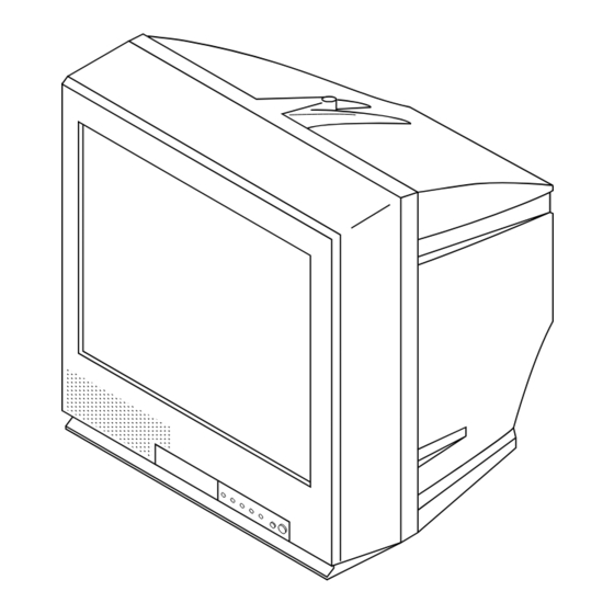
Summary of Contents for Sony Trinitron KV-PF14L7J
-
Page 1: Service Manual
SERVICE MANUAL BG-3S CHASSIS MODEL COMMANDER DEST. CHASSIS NO. MODEL COMMANDER DEST. CHASSIS NO. KV-PF14L7J RM-952 SCC-U30P-A KV-PF14P40 RM-952 Indonesia SCC-U20P-A KV-PF14P40 RM-952 Thailand SCC-U18Q-A TRINITRON COLOR TV ® http://cxema.ru... - Page 2 CARBON PAINTED ON THE CRT, AFTER REMOVING THE LIST ARE CRITICAL TO SAFE OPERATION. REPLACE THESE ANODE. COMPONENTS WITH SONY PARTS WHOSE PART NUMBERS APPEAR AS SHOWN IN THIS MANUAL OR IN SUPPLEMENTS PUBLISHED BY SONY. CIRCUIT ADJUSTMENTS THAT ARE CRITICAL TO SAFE OPERATION ARE IDENTIFIED IN THIS MANUAL.
-
Page 3: Table Of Contents
KV-PF14L7J/PF14P40 RM-952 TABLE OF CONTENTS Section Title Page Section Title Page SELF DIAGNOSIS FUNCTION 5. DIAGRAMS ........ 4 Block Diagram ............43 1. GENERAL ............Frame Schematic Diagram ........46 Circuit Boards Location .......... 48 2. DISASSEMBLY Schematic Diagrams and Printed Wiring Boards ... 49 2-1. -
Page 4: Self Diagnosis Function
KV-PF14L7J/PF14P40 RM-952 SELF DIAGNOSTIC FUNCTION The units in this manual contain a self-diagnostic function. If an error occurs, the STANDBY/TIMER lamp will automatically begin to flash. The number of times the lamp flashes translates to a probable source of the problem. A definition of the STANDBY/TIMER lamp flash indicators is listed in the instruction manual for the user’s knowledge and reference. -
Page 5: Disassembly
KV-PF14L7J/PF14P40 RM-952 DISPLAY OF STANDBY/TIMER LIGHT FLASH COUNT 2 times 5 times Lamp ON 0.3 sec. Lamp OFF 3 sec. Lamp OFF 0.3 sec. STANDBY/SLEEP lamp Diagnostic Item Flash Count* +B overcurrent/overvoltage 2 times Vertical deflection stopped White balance failure 5 times * One flash count is not used for self-diagnostic. - Page 6 KV-PF14L7J/PF14P40 RM-952 SELF-DIAGNOSTIC SCREEN DISPLAY For errors with symptoms such as “power sometimes shuts off” or “screen sometimes goes out” that cannot be confirmed, it is possible to bring up past occurances of failure for confirmation on the screen: [To Bring Up Screen Test] In standby mode, press buttons on the remote commander sequentially in rapid succession as shown below: [Screen display] / channel [5] / Sound volume [-] / Power ON ˘...
- Page 7 KV-PF14L7J/PF14P40 RM-952 SELF-DIAGNOSTIC CIRCUIT IC301 IC001 IC003 Y/CHROMA JUNGLE SYSTEM MEMORY FROM IK-IN IO-8DAT B-DAT FROM O-LED [+B] Q604 C3 PROTECT IO-SDAT [V] Q509/507 [+B overcurrent ªOCPº] Occurs when an overcurrent on the +B(135) line is detected by Q604. If Q604 go to ON and the voltage to pin 18 of IC301 should go down when V.SYNC is more than seven verticals in a period, the unit will automatically turn off.
-
Page 8: General
KV-PF14L7J/PF14P40 RM-952 – 8 – http://cxema.ru... - Page 9 KV-PF14L7J/PF14P40 RM-952 Using Your New TV – 9 – http://cxema.ru...
- Page 10 KV-PF14L7J/PF14P40 RM-952 Using Your New TV – 10 – http://cxema.ru...
- Page 11 KV-PF14L7J/PF14P40 RM-952 Using Your New TV – 11 – http://cxema.ru...
- Page 12 KV-PF14L7J/PF14P40 RM-952 Using Your New TV – 12 – http://cxema.ru...
- Page 13 KV-PF14L7J/PF14P40 RM-952 – 13 – http://cxema.ru...
- Page 14 KV-PF14L7J/PF14P40 RM-952 Using Your New TV – 14 – http://cxema.ru...
- Page 15 KV-PF14L7J/PF14P40 RM-952 – 15 – http://cxema.ru...
- Page 16 KV-PF14L7J/PF14P40 RM-952 – 16 – http://cxema.ru...
- Page 17 KV-PF14L7J/PF14P40 RM-952 – 17 – http://cxema.ru...
- Page 18 KV-PF14L7J/PF14P40 RM-952 – 18 – http://cxema.ru...
- Page 19 KV-PF14L7J/PF14P40 RM-952 – 19 – http://cxema.ru...
-
Page 20: Rear Cover Removal
KV-PF14L7J/PF14P40 RM-952 – 20 – http://cxema.ru... -
Page 21: Replacement Of Parts
KV-PF14L7J/PF14P40 RM-952 – 21 – http://cxema.ru... -
Page 22: Picture Tube Removal
KV-PF14L7J/PF14P40 RM-952 – 22 – http://cxema.ru... -
Page 23: Set-Up Adjustments
KV-PF14L7J/PF14P40 SECTION 3 RM-952 SET-UP ADJUSTMENTS • The following adjustments should be made when a complete Perform the adjustments in the following order : realignment is required or a new picture tube is installed. 1. Beam Landing • These adjustments should be performed with rated power 2. -
Page 24: Convergence
KV-PF14L7J/PF14P40 RM-952 3-2. CONVERGENCE Preparation : • Before starting this adjustment, adjust the focus, horizontal size V. STAT and vertical size. • Minimize the brightness setting. • Provide dot pattern. (1) Horizontal and Vertical Static Convergence Center dot H. STAT VR H. - Page 25 KV-PF14L7J/PF14P40 RM-952 (2) Dynamic Convergence Adjustment Preparation: • Before starting this adjustment, adjust the horizontal static convergence and the vertical static convergence on DY (3) Screen-corner Convergence Fix a Permalloy assy corresponding to the misconverged areas a-d : screen-corner misconvergence a to d : Permalloy assembly –...
-
Page 26: Focus Adjustment
KV-PF14L7J/PF14P40 RM-952 3-3. FOCUS ADJUSTMENT 3-4. G2 (SCREEN) AND WHITE BALANCE Adjust FOCUS control on the flyback transformer for the best ADJUSTMENTS 1. G2 (SCREEN) ADJUSTMENT focus. 1) Set the PICTURE to normal. 2) Put to VIDEO input mode without signals. 3) Connect R, G and B of the C3 board cathode to the oscillo- scope. -
Page 27: Circuit Adjustments
KV-PF14L7J/PF14P40 SECTION 4 RM-952 CIRCUIT ADJUSTMENTS 4-1. ADJUSTMENTS WITH COMMANDER Service adjustments are made with the RM-952 that comes with 1, 4 this unit. Select the adjustment item. ↓ a. ENTERING SERVICE MODE 3, 6 Raise/lower the data value. With the unit on standby ↓... -
Page 28: Adjustment Method
KV-PF14L7J/PF14P40 RM-952 4-2. ADJUSTMENT METHOD Item Number 00 of device GEO Use the same method for all Items. Use 1 and 4 to select the This explanation uses H-Position as an example. 1. Select “GEO 00 HPS” with the 1 and 4 buttons. adjustment item, use 3 and 6 to adjust, write with [MUTING] 2. - Page 29 KV-PF14L7J/PF14P40 RM-952 – 29 – http://cxema.ru...
- Page 30 KV-PF14L7J/PF14P40 RM-952 – 30 – http://cxema.ru...
- Page 31 KV-PF14L7J/PF14P40 RM-952 – 31 – http://cxema.ru...
- Page 32 KV-PF14L7J/PF14P40 RM-952 – 32 – http://cxema.ru...
- Page 33 KV-PF14L7J/PF14P40 RM-952 – 33 – http://cxema.ru...
- Page 34 KV-PF14L7J/PF14P40 RM-952 – 34 – http://cxema.ru...
- Page 35 KV-PF14L7J/PF14P40 RM-952 – 35 – http://cxema.ru...
- Page 36 KV-PF14L7J/PF14P40 RM-952 – 36 – http://cxema.ru...
- Page 37 KV-PF14L7J/PF14P40 RM-952 – 37 – http://cxema.ru...
- Page 38 KV-PF14L7J/PF14P40 RM-952 ITEM INFORMATION. No. OPB0 OP1 XTAL 4.43 XTAL 3.58 SECAM 2nd. Lang Item KV-PF14L7J KV-PF14P40 (Indonesia ) KV-PF14P40 (Thailand) No. OPB1 OP2 Item NICAM HDEV Thai Bil Dis Fav. DVD Input AV Input KV-PF14L7J KV-PF14P40 (Indonesia ) KV-PF14P40 (Thailand) No.
-
Page 39: Picture Quality Adjustments
KV-PF14L7J/PF14P40 RM-952 4-3. PICTURE QUALITY ADJUSTMENTS BELL FILTER ADJUSTMENT SUB COLOR ADJUSTMENT 1. Input SECAM color-bar signal. 2. Connect the dual-trace oscilloscope to the pin 9 (R-Y) of 1. Input a PAL color-bar. CN303 (not mounted). 2. Set to the following condition: 3. -
Page 40: Picture Distortion Adjustment
KV-PF14L7J/PF14P40 RM-952 4-5. PICTURE DISTORTION ADJUSTMENT Item Number 00 – 0B GEO 0 HSH (H POSITION) GEO 1 HSZ (H SIZE) GEO 2 PAP (PIN AMP) GEO 3 TILT (TRAPEZIUM) GEO 4 VSH (V POSITION) GEO 5 VSZ (V SIZE) GEO 6 SCR (VERTICAL S-Correction) GEO 7... - Page 41 http://cxema.ru...
- Page 42 http://cxema.ru...
-
Page 43: Block Diagram
KV-PF14L7J/PF14P40 RM-952 5-4. SCHEMATIC DIAGRAMS AND PRINTED WIRING BOARDS Note: • All capacitors are in µF unless otherwise noted. • All electrolytic capacitors are rated at 50V unless otherwise noted. • All resistors are in ohms. kΩ = 1000Ω, MΩ = 1000kΩ •... - Page 44 KV-PF14L7J/PF14P40 RM-952 A BOARD IC001 CXP86449-616S (KV-PF14P40 (Thailand)) A BOARD IC001 CXP86449-622S (KV-PF14L7J) A BOARD IC001 CXP86449-623S (KV-PF14P40 (EA)) CLOCK GENERATOR SPC700 CPU CORE A/D CONVERTER /SYSTEM CONTROL PA0~PA7 AN0~AN5 REMOCON FIFO PB0~PB7 12K/16K/24K/32K 352/704/1536 BYTES 40K/48K/60K BYTES SERIAL INTERFACE PC0~PC5 UNIT PC6~PC7...
- Page 45 http://cxema.ru...
-
Page 46: Frame Schematic Diagram
http://cxema.ru... - Page 47 http://cxema.ru...
-
Page 48: Circuit Boards Location
http://cxema.ru... -
Page 49: Schematic Diagrams And Printed Wiring Boards
http://cxema.ru... - Page 50 http://cxema.ru...
-
Page 51: Schematic Diagram Of A(1/2) Board
http://cxema.ru... - Page 52 http://cxema.ru...
- Page 53 http://cxema.ru...
-
Page 54: Scheamtic Diagram Of A(2/2) Board
KV-PF14L7J/PF14P40 RM-952 The components identified by shading and mark ! are critical for safety. Replace only with part number specified. REF. NO. PART NO. DESCRIPTION REMARK REF. NO. PART NO. DESCRIPTION REMARK D635 8-719-073-01 DIODE MA111-(K8).S0 JR006 1-216-295-91 SHORT D636 8-719-510-02 DIODE D1NS4 JR007... - Page 55 KV-PF14L7J/PF14P40 RM-952 The components identified by shading and mark ! are critical for safety. Replace only with part number specified. REF. NO. PART NO. DESCRIPTION REMARK REF. NO. PART NO. DESCRIPTION REMARK <IC LINK> Q312 8-729-216-22 TRANSISTOR 2SA1162-G (EXCEPT KV-PF14P40 (THAILAND)) PS200 1-532-675-21 LINK, IC 1.5A/150V...
- Page 56 KV-PF14L7J/PF14P40 RM-952 The components identified by shading and mark ! are critical for safety. Replace only with part number specified. REF. NO. PART NO. DESCRIPTION REMARK REF. NO. PART NO. DESCRIPTION REMARK R013 1-216-065-91 RES,CHIP 4.7K 1/10W R221 1-216-295-91 SHORT R014 1-216-025-91 RES,CHIP...
- Page 57 KV-PF14L7J/PF14P40 RM-952 The components identified by shading and mark ! are critical for safety. Replace only with part number specified. REF. NO. PART NO. DESCRIPTION REMARK REF. NO. PART NO. DESCRIPTION REMARK R377 1-216-121-91 RES,CHIP 1/10W R568 1-249-383-11 CARBON 1/4W F R378 1-216-031-00 RES,CHIP...
- Page 58 KV-PF14L7J/PF14P40 RM-952 The components identified by shading and mark ! are critical for safety. Replace only with part number specified. REF. NO. PART NO. DESCRIPTION REMARK REF. NO. PART NO. DESCRIPTION REMARK R659 1-216-049-91 RES,CHIP 1/10W <CRYSTAL> R660 1-216-073-00 RES,CHIP 1/10W R661 1-215-873-00...
- Page 59 KV-PF14L7J/PF14P40 RM-952 The components identified by shading and mark ! are critical for safety. Replace only with part number specified. REF. NO. PART NO. DESCRIPTION REMARK REF. NO. PART NO. DESCRIPTION REMARK <JACK> * A-1241-376-A F BOARD MOUNT **************** J701 ! 1-540-071-22 SOCKET, CRT 1-533-223-11 HOLDER, FUSE...
-
Page 60: Schematic Diagrams Of C3 And F Boards
KV-PF14L7J/PF14P40 RM-952 The components identified by shading and mark ! are critical for safety. Replace only with part number specified. REF. NO. PART NO. DESCRIPTION REMARK REF. NO. PART NO. DESCRIPTION REMARK ACCESSORIES AND PACKING MATERIALS *************************************** 1-417-151-21 MATCHING TRANSFORMER, ANTENNA 1-501-730-41 ANTENNA, TELESCOPIC 3-868-095-11... - Page 61 Replace only with part number specified. REF. NO. PART NO. DESCRIPTION REMARK REF. NO. PART NO. DESCRIPTION REMARK Sony Corporation English 99IS70187-1 SONY TV Industries (M) Sdn. Bhd. Printed in Malaysia 9-965-763-01 TV Business of General Area 1999. 9 – 80 – http://cxema.ru...
Need help?
Do you have a question about the Trinitron KV-PF14L7J and is the answer not in the manual?
Questions and answers