Table of Contents
Advertisement
Quick Links
INSTALLATION AND
OPERATING INSTRUCTIONS
FOR
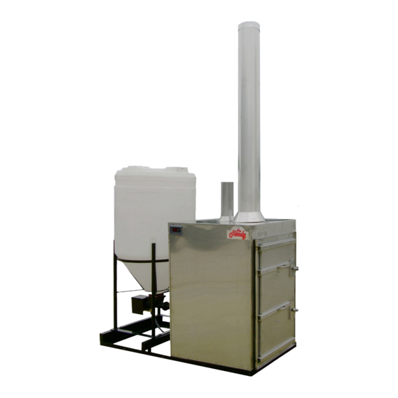
THE HARDY
OUTSIDE WOOD
BURNING HEATER
Model – KBP270
Model – KBP270
HARDY MANUFACTURING
HARDY MANUFACTURING
COMPANY, INC.
COMPANY, INC.
12345 ROAD 505
12345 ROAD 505
PHILADELPHIA, MS 39350
PHILADELPHIA, MS 39350
PHONE: (601) 656-5866
PHONE: (601) 656-5866
FAX: (601) 656-4559
FAX: (601) 656-4559
www.hardyheater.com
www.hardyheater.com
Rev. 2/22/2014
Advertisement
Table of Contents
Troubleshooting

Related Manuals for Hardy KBP270


Summary of Contents for Hardy KBP270
-
Page 1: Operating Instructions
INSTALLATION AND OPERATING INSTRUCTIONS THE HARDY OUTSIDE WOOD BURNING HEATER Model – KBP270 Model – KBP270 HARDY MANUFACTURING HARDY MANUFACTURING COMPANY, INC. COMPANY, INC. 12345 ROAD 505 12345 ROAD 505 PHILADELPHIA, MS 39350 PHILADELPHIA, MS 39350 PHONE: (601) 656-5866 PHONE: (601) 656-5866... - Page 2 THIS PAGE INTENTIONALLY LEFT BLANK...
- Page 3 Hardy experience and the input of Hardy customers in the production of a top quality heater. With the purchase of this Hardy Heater, you can now appreciate the high degree of craftsmanship and reliability that have made The Hardy the leader in the Outside Pellet burning Heater field.
- Page 4 If you should ever have a problem or question please refer to this manual or have it available when you call your Hardy Dealer or Hardy Manufacturing Company, Inc. HARDY MANUFACTURING COMPANY, INC.
-
Page 5: Safety Precautions
Always use proper care when installing, operating and maintaining the unit. Do not modify the unit. Do not substitute repairs which can be provided by your dealer, distributor, or Hardy Manufacturing Co. Inc. Failure to heed this warning or any additional warnings on the unit may result in an accident causing personal injury and loss of warranty. - Page 6 THE HARDY OUTSIDE PELLET BURNING HEATER How does an outside heater heat my home? The Hardy outside pellet burning heater is designed to save the most energy and provide the most comfortable heating available. It heats your home by heating a stainless steel tank filled with water, which surrounds the firebox of the outside heater.
-
Page 7: Table Of Contents
4-1 Connection to Hydronic System ......... 18 SECTION V: Plumbing Options for Domestic Water 5-1 Plate Heat Exchanger for Domestic Water ....19 SECTION VI: Heater Operation 6-1 Firing the Heater ............20 6-2 Burn Mode ..............21 6-3 Shut Down Mode ............22 (MODEL KBP270) - Page 8 8-3 Extended Period Shut Down and Start Up ....28 SECTION IX: Appendix 9-1 Modes of Operation Flow Diagram ......29 9-2 General Trouble Shooting Guide ......30 9-3 Module Specific Trouble Shooting Guide ....31 9-4 Maintenance Instructions ........32-40 (MODEL KBP270)
-
Page 9: Section I
MFS-20 AMP, MCA-20 AMP Clearance to Combustibles Top, Rear, Sides 18” Chimney Connector 18” Front 48” Flooring Non Combustible Water Capacity KBP270 – Holds Approximately 40 Gallons of Water Heater Dimensions Description Width Depth Height Weight KBP270 31” 75” 48”... - Page 10 Part No. Description 2007.30 Complete Feed Auger Assembly 2007.40 Process Control Module 2007.45 System Control Switch 2004.96 Control Switch Cover 2007.10 Firebox Door and Frame Assembly 3107.37 Outside Weather Resistant Insulated Cover HARDY MANUFACTURING CO., INC (MODEL KBP270) PAGE 2...
- Page 11 Stir Motor Assembly 2000.53 Process Control Relay 2000.55 Process Control Relay Socket 810.30 3/4” x 11.75” Raupex Pex A Pipe 810.32 3/4” x 2.5” Raupex Pex A Pipe 2007.13 Air/Power Transmission Assy 2004.00 GFCI HARDY MANUFACTURING CO., INC (MODEL KBP270) PAGE 3...
-
Page 12: Heater Component Parts
2007.11 Firebox Burn Chamber Assembly 2007.24 Stir Rod/Combustion Air Distribution Assy 2007.20 Front Bearing assembly 2007.70 Front Bearing Hi-Temp Assy 2007.12 Heat/Particulate Recovery Module. 2007.50 Firebrick Assy. 608.36 1” Brass Union Fitting. HARDY MANUFACTURING CO., INC (MODEL KBP270) PAGE 4... - Page 13 Feed Auger Motor Mount Assy 2007.37 Feed Auger Drive Assy. 2007.34 Feed Auger Hopper Tube Assy. 660.10 2” Union Fitting 2007.33 Feed Auger Tube. 2007.38 Feed Auger Flighting. 2007.49 Feed Auger Conduit Assy. HARDY MANUFACTURING CO., INC (MODEL KBP270) PAGE 5...
- Page 14 Heater Component Parts (Model KBP270) continued Optional Component Parts Water Legend Part No. Description 2007.85 Optional Day Hopper Assy 2007.86 Optional Tank Frame Assy HARDY MANUFACTURING CO., INC (MODEL KBP270) PAGE 6...
-
Page 15: Installation Of Heater
INSTALLATION OF HEATER Location of Heater The Hardy heater is designed to operate outside the structure to be heated. The unit must be located a minimum of 10 feet from the structure. The heating unit should be installed on a concrete pad with a recommended minimum dimension of 30”W x 75”L x 4”D . -
Page 16: Location Of Plumbing & Electrical Lines
(Note: The supply and return lines must be at least 3/4” pipe. 1” pipe may be required for longer distances. Some hydronic applications also require 1” pipe.) 3. One #12/2 W/Gnd NM type UF underground wire HARDY MANUFACTURING CO., INC (MODEL KBP270) PAGE 8... -
Page 17: Connection Of Power To Heater
CODE BLACK 200/BK BLUE 203/BL WATER LEVEL SENSOR GREEN 203/BL WATER LEVEL SENSOR 201/R ORANGE 202/O 100/BK WHITE 101/W PROCESS CONTROL MODULE RELAY PUMP RECEPTACLE 205/BL Combustion Blower 204/BK Auto Water Fill HARDY MANUFACTURING CO., INC (MODEL KBP270) PAGE 9... -
Page 18: Plumbing Connections
Use only copper, brass, or stainless steel fittings. Do not use galvanized or black iron. Supply to Heating System Heating System Return HARDY MANUFACTURING CO., INC (MODEL KBP270) PAGE 10... -
Page 19: Installation Of Smoke Stacks And Condenser Stack
Condenser Stack Opening. Seal perimeter of Condenser Stack Ring to Heater Hull using 6x8 Smoke Stack & Collar Silicone Sealant. Seal perimeter of Smoke Stack to Heater Hull using Silicone Sealant. Water HARDY MANUFACTURING CO., INC (MODEL KBP270) PAGE 11... -
Page 20: Filling The Heater With Water
15 parts per million or test the water supply for chloride to assure that the water supply does not exceed 45 parts per million. Call your Hardy dealer to obtain a chloride test on your water supply. If the chloride content of your local water supply exceeds the specifications mentioned above and necessitates the use of bottled or rain water, please do so to maintain the warranty of your heater . -
Page 21: Priming The Pump
Once the furnace has been filled with water you will need to prime the pumps. You will need to open the pump valve (Item 1) and the return valve (Item 2 ). Pump Valve Return Valve HARDY MANUFACTURING CO., INC (MODEL KBP270) PAGE 13... -
Page 22: Section Iii: Connection To Central Heating/Ac System
Locate the low voltage transformer that is providing you with 24 volt power. Find the common lead of this transformer and connect a wire to this lead and to terminal #8 of the new relay. HARDY MANUFACTURING CO., INC (MODEL KBP270) PAGE 14... -
Page 23: Connection Diagram
New thermostat terminal strip C connection terminal strip R connection terminal strip G connection existing thermostat R connection existing thermostat G connection terminal numbers of relay contacts HARDY MANUFACTURING CO., INC (MODEL KBP270) PAGE 15... -
Page 24: Location Of Heating Coil
Return Air Package System Supply Air Supply Air Install and Insulate Heating Coil in supply side of system and in a protected environment HARDY MANUFACTURING CO., INC (MODEL KBP270) PAGE 16... - Page 25 Air Flow Vertical Flow System Air Must be Air Flow Filtered before passing through Heating Coil. Horizontal Flow System Air Must be Air Flow Air Flow Filtered before passing through Heating Coil. HARDY MANUFACTURING CO., INC (MODEL KBP270) PAGE 17...
-
Page 26: Section Iv: Connection To Hydronic Heating Systems (Baseboard)
This unit must be wired by a qualified electrician in accordance with the National Electrical Code. The preferred method for connecting the Hardy Outside Pellet Burning Heater to an existing Hydronic system is by installing a p/n 300.01 40 plate heat exchanger w/ 1”... -
Page 27: Plumbing Options For Domestic Water
PLUMBING OPTIONS FOR DOMESTIC WATER Plate Heat Exchanger for Domestic Hot Water To add domestic hot water to the KBP270 model heater , a plate heat exchanger and pump can be added. This plate heat exchanger will provide preheated water to the domestic hot water. -
Page 28: Section Vi: Heater Operation
SECTION VI HEATER OPERATION Firing the Heater Hardy Manufacturing Company Inc.’s recommended fuel for this heater is Wood pellets. Proper storage of wood pellets is important for the proper operation of a pelletized Biofuel Burning Hydronic Heater. Fuel must be stored in a clean, dry environment and should be protected from contact with moisture, like rain, condensation, etc. -
Page 29: Burn Mode
Firebox Burn chamber. Light the pellets using a safe suitable method. Do not use any type of petroleum based products, charcoal starter, lighter fluid, or any other flammable accelerant to start your unit. HARDY MANUFACTURING CO., INC (MODEL KBP270) PAGE 21... -
Page 30: Shut Down Mode
The heater will remain in this mode of operation until the tank water temperature reaches 170º F. At this point the heater will enter into the Burn Mode of operation and all systems will be active. HARDY MANUFACTURING CO., INC (MODEL KBP270) PAGE 22... -
Page 31: Section Vii: Service Information
Fuel Usage Hardy Manufacturing recommends the use of wood pellets. Any fuels other than those specified will result in poor and erratic heater performance. This heater is designed to use a minimum amount of fuel but as with any heater of this type fuel usage is based upon the required load and temperature requirements. -
Page 32: Water Circulation System
Process Control Module Each mode of operation is determined by the Process Control Module. The Module constantly monitors the systems to switch between the different modes of operation as required. HARDY MANUFACTURING CO., INC (MODEL KBP270) PAGE 24... -
Page 33: Feed Auger Assembly
Control Panel. 7-12 Stir Shaft Assembly The Stir Shaft Assembly distributes fuel evenly throughout the firebox and also through its orifices provides the necessary combustion air for the fuel to burn properly. HARDY MANUFACTURING CO., INC (MODEL KBP270) PAGE 25... -
Page 34: Section Viii: Heater Maintenance
SECTION VIII HEATER MAINTENANCE The Hardy Heater is designed for ease of operation and ease of service. There is a minimal amount of maintenance that has to be done for proper operation of your new unit. Daily Maintenance 1. Make sure you have adequate fuel in the hopper. -
Page 35: Weekly Maintenance
Burn Chamber. Reinstall the Stir Shaft according to Stir Shaft Installation and removal instructions in Section 9-4. Failure to maintain the stir shaft will result in improper burning in the Firebox Burn Chamber. HARDY MANUFACTURING CO., INC (MODEL KBP270) PAGE 27... -
Page 36: Extended Period Shut Down And Start Up
Stir Shaft installation and Removal and Stir Shaft Maintenance instructions in Section 9-4. 8. Once all components have been verified, reconnect power connectors to all components. 9. Refer to firing the heater in section VI (6-1 through 6-3). HARDY MANUFACTURING CO., INC (MODEL KBP270) PAGE 28... -
Page 37: Appendix 9-1 Modes Of Operation Flow Diagram
Section IX APPENDIX Modes of Operation Flow Diagram Initial Start-Up Burn Mode Water Tem p w ater Tem p >170° F >172° F Shut Down w ater Tem p <=170° F HARDY MANUFACTURING CO., INC (MODEL KBP270) PAGE 29... -
Page 38: General Trouble Shooting Guide
Lack of combustion air in Firebox Refer to "Combustion Blower Assy" section of Module specific Troubleshooting (section 9-3) Also see "Stir Shaft Assy" section of Improper Burning in Module Specific Troubleshooting (Section Firebox. 9-3) HARDY MANUFACTURING CO., INC (MODEL KBP270) PAGE 30... -
Page 39: Module Specific Trouble Shooting Guide
Replace cartridge (see section 9-4; Pump pump does not troubleshooting) Circulating operate Defective pump capacitor Replace capacitor (see section 9-4; Pump Pump troubleshooting) Defective pump motor winding Replace Pump (see section 9-4; Pump troubleshooting) HARDY MANUFACTURING CO., INC (MODEL KBP270) PAGE 31... -
Page 40: Maintenance Instructions
Section VIII; 8-2 Firebox Verify Stir Rod Finger Orifices are Also See Stir shaft open with no restrictions. Removal Section & Stir Section VIII; 8-2 Remove and clean orifices as Shaft Cleaning Section required HARDY MANUFACTURING CO., INC (MODEL KBP270) PAGE 32... - Page 41 Loosen and remove the (qty 4) Hex nut from the underside of Feed Auger Hopper Top as Shown. Loosen the 2" Union located just in front of the Auger Hopper. HARDY MANUFACTURING CO., INC (MODEL KBP270) PAGE 33...
- Page 42 Pull the assembly away from Furnace Adapter coupling and then pull through the Hull Opening. Use caution when pulling the assembly through the Hull Opening to prevent damage to the Hull. Reinstall in reverse order. HARDY MANUFACTURING CO., INC (MODEL KBP270) PAGE 34...
- Page 43 Tube Assembly the Motor and Flighting can be completely removed from the tube by pulling toward you. To Remove the Auger Drive Shaft and Flighting Assemblies Loosen the Motor Set Screw using a 7/16" wrench. HARDY MANUFACTURING CO., INC (MODEL KBP270) PAGE 35...
- Page 44 Then tighten the 7/16" set screws on the clamp. Re-assemble in reverse order. HARDY MANUFACTURING CO., INC (MODEL KBP270) PAGE 36...
- Page 45 While rotating the stir rod by hand gently pull the rod toward you and remove from the heater. Re-assemble Drive shaft Assembly in reverse sequence of removal then re- assemble Stir Shaft Assembly in reverse sequence of removal. HARDY MANUFACTURING CO., INC (MODEL KBP270) PAGE 37...
- Page 46 While rotating the stir rod by hand gently pull the rod toward you and remove from the heater. Re-assemble Drive shaft Assembly in reverse sequence of removal then re- assemble Stir Shaft Assembly in reverse sequence of removal. HARDY MANUFACTURING CO., INC (MODEL KBP270) PAGE 38...
- Page 47 Remove rust from bearing end of stir shaft drive rod as shown using a wire brush or fine emory cloth. Re-install the stir shaft in reverse order of removal. HARDY MANUFACTURING CO., INC (MODEL KBP270) PAGE 39...
- Page 48 If the the pump does not show continuity across the two power wires or if either power wire shows continuity to ground the winding is defective and the pump should be replaced. HARDY MANUFACTURING CO., INC (MODEL KBP270) PAGE 40...
Need help?
Do you have a question about the KBP270 and is the answer not in the manual?
Questions and answers