Table of Contents
Advertisement
Quick Links
Advertisement
Table of Contents

Related Manuals for Hardy KB125


Summary of Contents for Hardy KB125
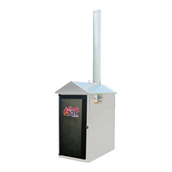
- Page 1 INSTALLATION AND OPERATING INSTRUCTIONS THE HARDY OUTSIDE WOOD BURNING HEATER Model – KB125 Model – KB125 HARDY MANUFACTURING COMPANY, INC. 12345 ROAD 505 PHILADELPHIA, MS 39350 PHONE: (601) 656-5866 FAX: (601) 656-4559 www.hardyheater.com Rev. 9/22/2014...
- Page 2 THIS PAGE INTENTIONALLY LEFT BLANK...
- Page 3 INTRODUCTION Thank you for purchasing the EPA Phase 2 qualified model KB125. The KB125 is an all stainless steel Hardy Outside Wood Fired Hydronic Heater. It represents the result of many years of Hardy experience and the input of Hardy customers in the production of a top quality heater.
- Page 4 If you should ever have a problem or question please refer to this manual or have it available when you call your Hardy Dealer or Hardy Manufacturing Company, Inc. HARDY MANUFACTURING COMPANY, INC.
- Page 5 Always use proper care when installing, operating and maintaining the unit. Do not modify the unit. Do not substitute repairs which can be provided by your dealer, distributor, or Hardy Manufacturing Co. Inc. Failure to heed this warning, any additional warnings on the unit, or instructions contained in this manual may result in an accident causing personal injury and/or loss of warranty.
- Page 6 THIS PAGE INTENTIONALLY LEFT BLANK (MODEL KB125)
- Page 7 2 feet Chimney height should be 2 feet above roof line. Residence served by furnace Minimum of 100 feet 6. Always remember to comply with all applicable state and local codes. Outdoor Furnace Manufacturers Caucus (MODEL KB125)
- Page 8 THE HARDY OUTSIDE WOOD FIRED HYDRONIC HEATER How does an outside heater heat my home? The Hardy outside wood fired hydronic heater is designed to save the most energy and provide the most comfortable heating available. It heats your home by heating a stainless steel tank filled with water, which surrounds the firebox of the outside heater.
- Page 9 Person(s) is/are also responsible for operation in a manner that does not create a public or private nuisance condition. The distance and stack height Hardy Mfg. recommends and the requirements in any applicable laws or other requirements may not always be adequate to prevent nuisance conditions due to terrain or other factors.
-
Page 10: Table Of Contents
4-1 Connection to Hydronic System ......... 17 SECTION V: Plumbing Options for Domestic Water 5-1 Plate Heat Exchanger for Domestic Hot Water ..18 SECTION VI: Heater Operation 6-1 Firing the KB125 ............19 6-2 Loading the KB125 ............ 20 (MODEL KB125) viii... - Page 11 7-10 Low Water Lockout Relay ........22 7-11 Timer ................ 22 7-12Time Delay Relay............22 SECTION VIII: Heater Maintenance 8-1 Weekly Maintenance..........23 8-2 Monthly Maintenance ..........24 8-3 Extended Period Shut Down and Start Up ....25 (MODEL KB125)
-
Page 12: General Information
Clearance to Combustibles Top, Rear, Sides 18” Chimney Connector 18” Front 48” Flooring Non Combustible Water Capacity KB125 – Holds Approximately 80 Gallons of Water Heater Outside Dimensions Model Width Depth Height Weight KB125 - 120,000 BTU 32 1/2” 61”... -
Page 13: Heater Component Parts
Time Delay Relay 2001.05 Damper Solenoid 2000.53 (2) Low Water Lockout Relay 2000.55 (2) Socket For Low Water Lockout Relay 607.42 3/4” Boiler Fill/Drain (Not Visible) 607.45 (3) 1” Brass Ball Valve HARDY MANUFACTURING CO., INC (MODEL KB125) PAGE 2... - Page 14 Heater Component Parts Model KB125 Standard Components (continued) Legend Part No. Description 2065.50 (15) Turbulators 7165.99 Bypass Damper HARDY MANUFACTURING CO., INC (MODEL KB125) PAGE 3...
- Page 15 Heater Component Parts Model KB125 Standard Components (continued) Legend Part No. Description 3105.17 (4) Refractory Grates 2165.31 (2) Front & Back Fire Bricks HARDY MANUFACTURING CO., INC (MODEL KB125) PAGE 4...
-
Page 16: Installation Of Heater
INSTALLATION OF HEATER Location of Heater The Hardy Heater is designed to operate outside the structure to be heated. The unit must be located a minimum of 10 feet from any structure. The heating unit should be installed on a concrete pad with a recommended minimum dimension of 34”W x 61”L x 4”D. -
Page 17: Chimney Connection
1. One 1” water supply line to heating system 2. One 1” water return line from heating system (Note: The supply and return lines must be 1” pipe .) 3. One #12/2 w/gnd NM type UF underground wire HARDY MANUFACTURING CO., INC (MODEL KB125) PAGE 6... -
Page 18: Connection Of Power To Heater
Receptacle located on the rear of the Heater. The breaker installed at the power source should be a 20 amp GFCI. Wiring Diagram This equipment must be installed in accordance with the National Electrical Code. ( See wiring diagram next page ) HARDY MANUFACTURING CO., INC (MODEL KB125) PAGE 7... - Page 19 Wiring Diagram (continued) HARDY MANUFACTURING CO., INC (MODEL KB125) PAGE 8...
-
Page 20: Plumbing Connections
Heater with hull and stacks removed to show connections Hardy P/N 300.01 40 Plate Heat Exchanger with 1" fittings Existing Boiler Close this valve Heat Heat Existing Zone Zone Pump HARDY MANUFACTURING CO., INC (MODEL KB125) PAGE 9... - Page 21 Installation of Smoke Stacks The KB125 comes with two three foot sections of smoke stack and a stack ring. Push the two smoke stacks into one another. Then place the stack ring onto the top section. Last install the combined stacks into the units flu gas exit hole on the roof. Pay close attention while working above the unit top when installing the stacks.
-
Page 22: Filling The Heater With Water
45 parts per million. Call your Hardy dealer to obtain a chloride test on your water supply. If the chloride content of your local water supply exceeds the specifications mentioned above this necessitates the use of bottled or rain water, please do so to maintain the warranty of your heater . -
Page 23: Priming The Pump
Air Flow Heater with hull and stacks removed to show connections Vertical Flow System Air Must be Air Flow Filtered before passing through Heating Coil. HARDY MANUFACTURING CO., INC (MODEL KB125) PAGE 12... -
Page 24: Section Iii: Connection To Central Heating/Ac System
Locate the low voltage transformer that is providing you with 24 volt power. Find the common lead of this transformer and connect a wire to this lead and to terminal #8 of the new relay. HARDY MANUFACTURING CO., INC (MODEL KB125) PAGE 13... - Page 25 New thermostat terminal strip C connection terminal strip R connection terminal strip G connection existing thermostat R connection existing thermostat G connection terminal numbers of relay contacts HARDY MANUFACTURING CO., INC (MODEL KB125) PAGE 14...
-
Page 26: Location Of Heating Coil
Return Air Package System Supply Air Supply Air Install and Insulate Heating Coil in supply side of system and in a protected environment HARDY MANUFACTURING CO., INC (MODEL KB125) PAGE 15... - Page 27 Vertical Flow System Air Must be Air Flow Filtered before passing through Heating Coil. Horizontal Flow System Supply Return Air Must be Air Flow Air Flow Filtered before passing through Heating Coil. HARDY MANUFACTURING CO., INC (MODEL KB125) PAGE 16...
-
Page 28: Section Iv: Connection To Hydronic Heating Systems (Baseboard)
This unit must be wired by a qualified electrician in accordance with the National Electrical Code. The preferred method for connecting the Hardy KB125 Hydronic Heater to an existing hydronic system is by installing a p/n 300.01 (40 plate heat exchanger w/ 1” fittings) into the return line of the existing boiler system. -
Page 29: Plumbing Options For Domestic Water
PLUMBING OPTIONS FOR DOMESTIC WATER Plate Heat Exchanger for Domestic Hot Water To add domestic hot water to the KB125 hydronic heater, a plate heat exchanger and pump can be added. This plate heat exchanger will provide preheated water to the domestic hot water. -
Page 30: Section Vi: Heater Operation
HEATER OPERATION Firing the KB125 Hardy Manufacturing recommends burning clean seasoned oak hardwood in this heater: Clean Wood means wood that has no paint, stains, or other types of coatings, and wood that has not been treated with preservatives, including but not limited to, copper chromium arsenate, creosote, or pentachlorophenol. -
Page 31: Loading The Kb125
Loading the KB125 The following steps should be completed to load the KB125 Hardy Heater: 1. Open the bypass damper (located on the left side of the firebox door). 2. Open the firebox door. 3. Flip the blower switch off (located on the left side of the heater), light will turn on. This will begin the off delay timer that is set for 5 minutes. -
Page 32: Section Vii: Service Information
Fuel Usage Hardy Manufacturing recommends the use of clean seasoned oak hardwood. Any fuels other than those specified will result in poor and erratic heater performance. This heater is designed to use a minimum amount of fuel but as with any heater of this type fuel usage is based upon the required load and temperature requirements. -
Page 33: Combustion Air Blower Assembly
This prevents short cycling of the unit. 7-12 Time Delay Relay The time delay relay is energized by the timer. It turns off the control power to draft dampers and the blower. HARDY MANUFACTURING CO., INC (MODEL KB125) PAGE 22... -
Page 34: Section Viii: Heater Maintenance
SECTION VIII HEATER MAINTENANCE The Hardy heater is designed for ease of operation and ease of service. There is a minimal amount of maintenance that has to be done for proper operation of your new unit. Weekly Maintenance The following steps should be completed weekly to clean the KB125 Hardy Heater: 1. -
Page 35: Monthly Maintenance
Monthly Maintenance The following steps should be completed monthly to clean the KB125 Hardy Heater: 1. Burn down wood in the firebox to a coal bed. 2. Open the bypass damper (located on the front left side of the heater). -
Page 36: Extended Period Shut Down And Start Up
2. Confirm all door gasket seals are clean and secured to form an air tight seal onto the door frame. 3. Refer to Section 6-1 & 6-2 instructions HARDY MANUFACTURING CO., INC (MODEL KB125) PAGE 25...
Need help?
Do you have a question about the KB125 and is the answer not in the manual?
Questions and answers