Table of Contents
Advertisement
Quick Links
HLLY ELECTRONICS (Hongkong) CO., LTD
FM Transmitter instruction manual
Mode: HLLY TX-01S
v1.0
———————————————————————————————————————————
—————
Code Switch -
Antenna – Rotate to Lock
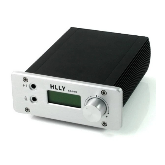
Front Panel
Push to confirm,adjust via rotate
———————————————————————————————————————————
—————
1)Operation Manual:
1. First link the antenna to transmitter,then the power supply,LCD will display "OFF"
(PIC01)。
Advertisement
Table of Contents

Related Manuals for HLLY Electronics HLLY TX-01S

Summary of Contents for HLLY Electronics HLLY TX-01S
- Page 1 HLLY ELECTRONICS (Hongkong) CO., LTD FM Transmitter instruction manual Mode: HLLY TX-01S v1.0 ——————————————————————————————————————————— ————— Code Switch - Antenna – Rotate to Lock Front Panel Push to confirm,adjust via rotate ——————————————————————————————————————————— ————— 1)Operation Manual: 1. First link the antenna to transmitter,then the power supply,LCD will display “OFF”...
- Page 2 HLLY ELECTRONICS (Hongkong) CO., LTD (PIC01) (PIC02) Push the code switch knob, the transmitter will enter the main menu. It display current broadcast Frequency, Volume state, and power level (PIC02) , in main menu state, User can adjust the volume by rotating the switch,the volume rang value is from 00 to 79.
- Page 3 HLLY ELECTRONICS (Hongkong) CO., LTD (PIC09) (PIC10) 5 MENU ST or MO –Stereo and Mono Adjusting(PIC11) (PIC11) (PIC13) (PIC12) 6 MENU SN: Device SN display(PIC14) ,Device Unique number, Factory settings, can not be changed. (PIC14) (PIC15) 10. 7 EXIT For Exiting Menu(PIC16) Pushing and Exit Menu (PIC16)...
- Page 4 HLLY ELECTRONICS (Hongkong) CO., LTD 2)Parameters Power supply: DC12V Maximum operating current: 500mA Ambient temperature: -5~40℃ Frequency Range: 76MHz~108MHz Frequency Step 100KHz Frequency Stabilize Style: Pre-emphasize Default 50µs Optional 75µs Output power: 0 to 1000mW±10% Output resistance: 50 OHM 10. Modulate Style:...
- Page 5 HLLY ELECTRONICS (Hongkong) CO., LTD Power curve diagram when different power level Table 1.0 Power curve diagram when different Frequency...
- Page 6 HLLY ELECTRONICS (Hongkong) CO., LTD Spectrum Testing Picture: Note : This is the spectrum picture when transmitter Note :This is the spectrum picture when transmitter work work at 76Mhz , There is no stray radiation,But at 87Mhz ,, There is no stray radiation and signal is very second harmonics is obviously , second harmonics clear.
Need help?
Do you have a question about the HLLY TX-01S and is the answer not in the manual?
Questions and answers