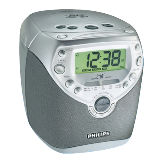
Philips AJ3950 Service Manual
Cd clock radio
Hide thumbs
Also See for AJ3950:
- Quick start manual (5 pages) ,
- Specifications (2 pages) ,
- User manual (2 pages)
Table of Contents
Advertisement
CD Clock Radio
TABLE OF CONTENTS
Handling chip components and safety
Technical Specification & Service Tools
..................................................
Service Measurement
................................................
Connections & Controls
.................................................
Instructions for use
...................................................
Disassembly Diagram
........................................
CD Service Test Program
.............................................................
Block Diagram
...........................................................
Wiring Diagram
MAIN BOARD (Part 1)
.......................................................
circuit diagram
.......................................................
layout diagram
MAIN BOARD (Part 2)
.......................................................
circuit diagram
.......................................................
layout diagram
Safety regulations require that the set be restored to its original
condition and that parts which are identical with those specified
be used.
C
Copyright 1995 Philips Consumer Electroncis B.V. Eindhoven, The Netherlands
All rights reserved. No part of this publication may be reproduced, stored in a retrieval
system or transmitted, in any form or by any means, electronic, mechanical, photocopying,
or otherwise without the prior permission of Philips.
Published by SS 0109 Service Audio
PCS 107 248
chapter
.............................
1 - 1
..........................
2 - 1
2 - 2
3 - 1
3 - 2 to 3 - 4
4 - 1
4 - 2 to 4 - 3
5 - 1
6 - 1
7 - 1
7 - 2
8 - 1
8 - 2
Printed in The Netherlands
TUNER BOARD
.......................................................
circuit diagram
.......................................................
layout diagram
CD MODULE
......................................................
layout diagram
......................................................
circuit diagram
EXPLODED VIEWS DIAGRAM
.................................................................
cabinet
.....................................................
Mechanical partslist
...............................................
Electrical partslist
Copyright reserved
Subject to modification
AJ3950
all versions
chapter
9 - 1
9 - 2
10 - 1
10 - 2
11 - 1
11 - 1
12 - 1 to 12 - 5
CLASS 1
LASER PRODUCT
3140 785 22570
GB
Advertisement
Table of Contents

Subscribe to Our Youtube Channel
Related Manuals for Philips AJ3950


Summary of Contents for Philips AJ3950
- Page 1 LASER PRODUCT Copyright 1995 Philips Consumer Electroncis B.V. Eindhoven, The Netherlands All rights reserved. No part of this publication may be reproduced, stored in a retrieval system or transmitted, in any form or by any means, electronic, mechanical, photocopying, or otherwise without the prior permission of Philips.
-
Page 2: Handling Chip Components
HANDLING CHIP COMPONENTS © ñ WARNING WAARSCHUWING All ICs and many other semiconductors are susceptible to Alle IC´s en vele andere halfgeleiders zijn gevoelig voor electrostatic discharges (ESD). Careless handling during electrostatische ontladingen (ESD). repair can reduce life drastically. Onzorgvuldig behandelen tijdens reparatie kan de levensduur When repairing, make sure that you are connected with the drastisch doen vermindern. -
Page 3: Technical Specifications
TECHNICAL SPECIFICATIONS TUNER - AM SECTION GENERAL Tuning range MW : 526.5 – 1606.5 kHz Mains voltage -/00 : 220 - 230 V -/17 : 520 - 1722 kHz -/17 : 120v IF frequency : 468 kHz ± 3 kHz Mains frequency -/00 : 50 Hz Sensitivity... -
Page 5: Connections And Controls
CONNECTIONS AND CONTROLS PCS 107 250... - Page 6 INSTRUCTIONS FOR USE PCS 107 251...
- Page 7 INSTRUCTIONS FOR USE PCS 107 252...
- Page 8 INSTRUCTIONS FOR USE PCS 107 253...
-
Page 9: Disassembly Diagram
DISASSEMBLY DIAGRAM A. To remove Rear Cabinet B. To remove Speaker Frame C. To remove CD Tray and Middle Bracket D. To remove Middle Bracket E. To remove Main Board F. To remove Repeat Alarm Key PCS 107 254... -
Page 10: Cd Service Test Program
CD SERVICE TEST PROGRAM For entering the Factory and Service mode keep BAND and NEXT keys pressed while power up (plug-in) the set. The set will enter CD repeat all mode. CD TEST For entering the Factory and Service mode keep BAND and PREV keys pressed while power up (plug-in) the set. To enter Service The set will enter CD repeat one mode. - Page 11 Abbreviations and Pin-description of CD Ics Abbreviations and Pin-description of CD Ics SERVO PROCESSOR SAA7325H SERVO PROCESSOR SAA7325H SYMBOL DESCRIPTION SYMBOL DESCRIPTION HFREF comparator common mode input microcontroller interface R/W and load control line input (4-wire bus mode) HFIN comparator signal input SILD microcontroller interface R/W and load control line input (4-wire bus mode) ISLICE...
-
Page 12: Block Diagram
BLOCK DIAGRAM PCS 107 256... -
Page 13: Wiring Diagram
WIRING DIAGRAM PCS 107 257... -
Page 14: Circuit Diagram
MAIN BOARD (Part 1) - CIRCUIT DIAGRAM PCS 107 258... -
Page 15: Layout Diagram
MAIN BOARD (Component Side View) - LAYOUT DIAGRAM CD KEYBOARD - LAYOUT DIAGRAM LED BOARD - LAYOUT DIAGRAM KEYBOARD - LAYOUT DIAGRAM KEYBOARD (TOP) - LAYOUT DIAGRAM PCS 107 259... - Page 16 MAIN BOARD (Part 2) - CIRCUIT DIAGRAM PCS 107 260...
- Page 17 MAIN BOARD (Copper Side View) - LAYOUT DIAGRAM POWER BOARD - LAYOUT DIAGRAM CD DOOR SWITCH - LAYOUT DIAGRAM PCS 107 261...
-
Page 18: Tuner Board Atm5 - Circuit Diagram
TUNER BOARD ATM5 - CIRCUIT DIAGRAM 1001 A4 1104 E3 1110 B11 5107a 5107b 5107c 2101 A4 SFE10.7MS3 SFE10.7MS2 CDA10.7MC1 T003 1001 FM-RF All SMD Transistors 2102 A4 180KHz 230KHz 2103 D4 2104 G7 2105 A5 2106 F10 7102 2108 C3 Top View from BC847B Solder Side... -
Page 19: Tuner Board Atm5 - Layout Diagram
TUNER BOARD ATM5 - LAYOUT DIAGRAM TUNER ADJUSTMENT TABLE FM/MW versions Waverange Input Frequency Input Set tuned to Adjust Measure on Scope / Counter 1001 E1 2122 1104 A2 3101 OSCILLATOR 1110 F6 5101 2103 D2 5102 lower band end 5104 87,35 MHz 2104 D1... - Page 20 10-1 10-1 CD99 DA11 - LAYOUT DIAGRAM 1800 3703 3876 CD99 Board component side view CD99 Board copper side view 1801 3704 3877 1810 3705 3878 1821 3728 3879 1822 3745 3880 2840 5802 1823 3750 3881 1824 3751 3882 2701 3757 3883...
- Page 21 10-2 10-2 10-2 CD99 DA11 - CIRCUIT DIAGRAM 1800 D1 2806 E4 2813 E9 2820 B10 2827 C14 2834 F5 2841 C1 2865 D5 2875 D5 3801 A1 3808 A2 3815 E5 3822 E7 3829 A11 3838 D14 3845 G12 3852 F5 3859 H5 3890 B4...
-
Page 22: Mechanical Partslist
4 (3x) 419 9965 000 07665 Stabilizer Bracket 421 9965 000 07685 CD Door Spring 4 (2x) 422 9965 000 07687 CD Door Inlay (B) (For AJ3950) 1 (10x) 1 (3x) 422 9965 000 07861 CD Door Inlay (D) (For AJ3951/AJ3952) -
Page 23: Electrical Partslist - Main Board
12-1 ELECTRICAL PARTSLIST - MAIN BOARD - COILS, CRYSTAL & FILTER - - IC & TRANSISTORS - J116 9965 000 05605 Inductor 1µH Q227 9965 000 07691 Trans 2SA608NG-NPA-AT L101 9965 000 05605 Inductor 1µH L102 9965 000 05605 Inductor 1µH - MISCELLANEOUS - L103 9965 000 05604 Axial Inductor 100µH... -
Page 24: Electrical Partslist - Keyboard
12-2 ELECTRICAL PARTSLIST - KEYBOARD ELECTRICAL PARTSLIST - TUNER BOARD - LED - - CAPACITOR - D110 4822 130 10668 LED L-934SGC (Green) 2106 9965 000 07711 PVC 160/82+20X2 D111 4822 130 10668 LED L-934SGC (Green) D112 4822 130 10668 LED L-934SGC (Green) - RESISTOR - - MISCELLANEOUS - 3101... -
Page 25: Electrical Partslist - Cd99 Da11
12-3 ELECTRICAL PARTSLIST - CD99 DA11 - CAPACITORS - - CAPACITORS - 2801 482212441751 47µF 2855 482212411912 220µF 20% 6,3V 2802 482212441751 47µF 2857 482212412362 47µF 4V 20% 2803 482212613695 82pF 1% NP0 63V 2860 532211680853 560pF 5% NP0 63V 2804 482212613695 82pF 1% NP0 63V... - Page 26 12-4 ELECTRICAL PARTSLIST - CD99 DA11 - RESISTORS - - RESISTORS - 3826 482205120273 0,1W 3883 482205110102 1K 2% 0,25W 3827 482205120339 0,1W 3884 482205110102 1K 2% 0,25W 3828 482205120479 0,1W 3886 482211710833 0,1W 3829 482205120101 100R 0,1W 3887 482211710833 0,1W 3830 482205120472...
- Page 27 12-5 ELECTRICAL PARTSLIST - CD99 DA11 - RESISTORS - 4888 482205120008 Jumper 4889 482205120008 Jumper - COILS & FILTERS - 1810 482224273557 Filter CST8,46MTW-TF01 5803 482215711231 Coil LAN02TB1R0J - DIODES - 6877 482213011564 Diode UDZ3.9B - IC & TRANSISTORS - 7800 482220917324 IC SAA7325H...
Need help?
Do you have a question about the AJ3950 and is the answer not in the manual?
Questions and answers