
Related Manuals for Cumberland PNEG-1640

Summary of Contents for Cumberland PNEG-1640
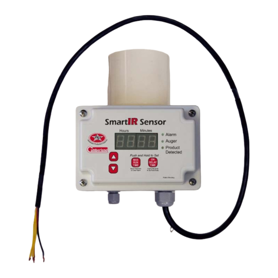
- Page 1 Smart IR Sensor Installation and Operation Manual PNEG-1640 Date: 12-21-11 PNEG-1640...
- Page 2 PNEG-1640 Smart IR Sensor...
-
Page 3: Table Of Contents
Chapter 8 Replacement Parts ..........................16 Smart IR Sensor Assembly (FLX-4951) ....................16 Chapter 9 Wiring Diagrams ..........................18 Alarm Wiring Diagram ..........................18 AP Wiring Diagram ..........................19 Choretime Wiring Diagram ........................21 Universal Wiring Diagram ........................22 Chapter 10 Warranty ............................23 PNEG-1640 Smart IR Sensor... -
Page 4: Chapter 1 Safety
CAUTION, used with the safety alert symbol, indicates a CAUTION hazardous situation which, if not avoided, could result in minor or moderate injury. NOTICE is used to address practices not related to NOTICE personal injury. PNEG-1640 Smart IR Sensor... - Page 5 A respirator may be needed to prevent breathing potentially toxic fumes and dust. Wear a hard hat to help protect your head. Hard Hat Wear appropriate fall protection equipment when working at elevations greater than six feet (6'). Fall Protection PNEG-1640 Smart IR Sensor...
-
Page 6: Chapter 2 Application
The sensor is installed underneath a control unit between the powerhead drop (funnel) and the drop tube at the end of a Flex-Flo feed system. Figure 2A PNEG-1640 Smart IR Sensor... -
Page 7: Chapter 3 Installation
3-1/4" O.D. Use two (2) #10 x 3/4" self-drilling screws (S-8045) (supplied) to fasten the Smart IR Sensor to the powerhead drop funnel and drop tube as shown in Figure Figure 3A PNEG-1640 Smart IR Sensor... -
Page 8: Chapter 4 Basic Operation
It also includes a maximum run timer that will shut the system down if the auger runs too long in case of an empty or bridged feed tank or a feed spill. Alarm contacts are available to provide remote notification of a maximum run situation. Figure 4A Full Figure 4B Maximum Run Time Alarm PNEG-1640 Smart IR Sensor... -
Page 9: Chapter 5 Delay Time
The range of delay time setting for the Smart IR Sensor is from 0 hours and 0 minutes to 23 hours and 59 minutes. Check Delay Time Setting To check the delay time setting, at any time, push and hold the “On Delay Time” button. Figure 5A Checking Delay Time PNEG-1640 Smart IR Sensor... -
Page 10: Setting/Adjusting The Delay Time
To make the auger start immediately, by-pass the delay time for one cycle only, by pressing and holding the “On Delay Time” button down for 5 second. PNEG-1640 Smart IR Sensor... -
Page 11: Chapter 6 Run Time
Then add approximately 10 minutes to this time to account for variability. The range of adjustment for the maximum run time is from 1 minute to 23 hours and 59 minutes. PNEG-1640 Smart IR Sensor... -
Page 12: Check Maximum Run Time Setting
“arrow up” or “arrow down” button. Each time an “arrow” button is pushed, the time will change by 1 minute. To make the time scroll faster, continue to hold the “arrow” button down for several seconds. Figure 6C Adjusting the Maximum Run Time PNEG-1640 Smart IR Sensor... -
Page 13: Maximum Run Time Operation
1. At the Smart IR Sensor, push and hold the “Maximum Run Time” button for 5 seconds. 2. At the Flex-Flo control unit, switch the toggle “off” then back “on” again. 3. At the main circuit board, switch the controlling circuit breaker “off” then back “on” again. PNEG-1640 Smart IR Sensor... -
Page 14: Chapter 7 Sensitivity
If the sensor fails to operate properly, disconnect the sensor from the powerhead drop above and use a soft cloth to clean the dust from inside. If it still does not operate properly, contact the nearest AP/Cumberland dealer to aid in troubleshooting. PNEG-1640 Smart IR Sensor... - Page 15 NOTES PNEG-1640 Smart IR Sensor...
-
Page 16: Chapter 8 Replacement Parts
8. Replacement Parts Smart IR Sensor Assembly (FLX-4951) PNEG-1640 Smart IR Sensor... -
Page 17: Replacement Parts
FLX-5000 Infrared Sensor Housing Assembly FLX-5002 Infrared Sensor Insert Assembly FLX-5003 Infrared Sensor Power Board Assembly FLX-5001 Infrared Sensor Connector Cable FLX-5004 Infrared Sensor Face Plate Assembly S-8045 Screw, SDS #10 x 3/4" HWH SS 410 PNEG-1640 Smart IR Sensor... -
Page 18: Chapter 9 Wiring Diagrams
9. Wiring Diagrams Alarm Wiring Diagram PNEG-1640 Smart IR Sensor... -
Page 19: Ap Wiring Diagram
9. Wiring Diagrams AP Wiring Diagram PNEG-1640 Smart IR Sensor... - Page 20 9. Wiring Diagrams AP Wiring Diagram (Continued) PNEG-1640 Smart IR Sensor...
-
Page 21: Choretime Wiring Diagram
9. Wiring Diagrams Choretime Wiring Diagram PNEG-1640 Smart IR Sensor... -
Page 22: Universal Wiring Diagram
9. Wiring Diagrams Universal Wiring Diagram PNEG-1640 Smart IR Sensor... -
Page 23: Chapter 10 Warranty
GSI. Prior to installation, the end-user has the responsibility to comply with federal, state and local codes which apply to the location and installation of products manufactured or sold by GSI. 9101239_1_CR_rev7.DOC (revised July 2009) PNEG-1640 Smart IR Sensor... - Page 24 This equipment shall be installed in accordance with the current installation codes and applicable regulations which should be carefully followed in all cases. Authorities having jurisdiction should be consulted before installations are made. This product covered by U.S. Patent # 8,056,506. 1004 E.
Need help?
Do you have a question about the PNEG-1640 and is the answer not in the manual?
Questions and answers