Table of Contents
Advertisement
Quick Links
Installation and
Operating Instructions
Changes or modifications not expressly approved by the party responsible for compliance could void
the user's authority to operate this device. This device complies with part 15 of the FCC Rules.
Operation is subject to the condition that this device does not cause harmful interference.
This equipment has been tested and found to comply with the limits for a Class A digital device,
pursuant to part 15 of the FCC Rules. These limits are designed to provide reasonable protection
against harmful interference when the equipment is operated in a commercial environment. This
equipment generates, uses, and can radiate radio frequency energy and, if not installed and used in
accordance with the instruction manual, may cause harmful interference to radio communications.
To obtain the latest manual and template revisions or to view installation and programming videos
go to www.ADAEZ.com.
For technical support call (877) 232-3987.
© 2012 ADA EZ. ALL RIGHTS RESERVED.
ADA EZ Pro
Installation and Operating Instructions
700002 Rev. F
EZ040
Note
700002 Rev. F
1 of 56
Advertisement
Table of Contents

Summary of Contents for Ada Ez Pro 700002
-
Page 1: Operating Instructions
To obtain the latest manual and template revisions or to view installation and programming videos go to www.ADAEZ.com. For technical support call (877) 232-3987. 700002 Rev. F 1 of 56 © 2012 ADA EZ. ALL RIGHTS RESERVED. -
Page 2: Table Of Contents
10.1 Troubleshooting Recommendations ......................46 Attachments Attachment 1, Documents, Definitions, Tools, Equipment, and Consumables ..........49 Attachment 2, Quick Programming Guide ......................50 Attachment 3, ADA EZ Installation Schematics ....................52 700002 Rev. F 2 of 56 © 2012 ADA EZ. ALL RIGHTS RESERVED. -
Page 3: Purpose
80/25 guideline: Apply ADA EZ to a door that will be cycled manually a minimum of 80 times per day and cycled automatically approximately 25% or less per day. When applied using this 80/25 guideline the ADA EZ will self-generate all the power it needs to keep its field-replaceable onboard battery pack charged for up to 12 years and in some cases longer. -
Page 4: Prerequisites
An incomplete installation or unprogrammed operator can cause a safety hazard.. Follow all instructions carefully. For questions call ADA EZ Technical Support at the number listed on the front of this document. -
Page 5: System Description
SYSTEM DESCRIPTION General The ADA EZ operator is shipped in the following pieces (see Figure 1): Operator assembled with black cover installed Optional silver and brown covers (when specified) Door arm assembly Operator mounting bracket ... - Page 6 Figure 1. ADA EZ Shipped Components 700002 Rev. F 6 of 56 © 2012 ADA EZ. ALL RIGHTS RESERVED.
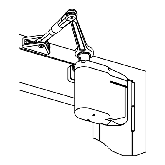
- Page 7 Figure 2 illustrates an assembled ADA EZ operator installed on a left hand door. The paragraphs that follow describe its components: Figure 2. ADA EZ Assembly (Typical) 700002 Rev. F 7 of 56 © 2012 ADA EZ. ALL RIGHTS RESERVED.
- Page 8 Transmitter: An external device that emits an rf signal or an electrical signal to operate the door. When pushed once, the door opens. The transmitter has a range of 85 (26 m) 700002 Rev. F 8 of 56 © 2012 ADA EZ. ALL RIGHTS RESERVED.
-
Page 9: Features And Functions
Closing Force: The door shall not close with a force greater than 15 lbs (6.8 kg) when measured at the latch side of the closing stile. For ADA EZ series, the closing force is adjustable to 8 lbs (3.6 kg). -
Page 10: Determining The Correct Operator Application
The operator must only be installed on doors and frames that are in good working order. The door must not stick or bind during normal operation. If applicable, the existing door closer must be removed before installing the ADA EZ operator. The operator must be completely installed and programmed or the door must be disabled prior to leaving the site. - Page 11 RIGHT HAND DOOR. 2. For the ADA EZ operator, a LH door uses a left hand operator and a RH door uses a right hand operator.
-
Page 12: Operator And Door Arm Installation Instructions-Push-Side Applications
If the door is a narrow-stile door, USE the solid line mounting location. If the door is an application other than a narrow-stile door, USE the dotted line mounting location. 700002 Rev. F 12 of 56 © 2012 ADA EZ. ALL RIGHTS RESERVED. - Page 13 Figure 6. Determining Which Mounting Template Fold Line to Use 700002 Rev. F 13 of 56 © 2012 ADA EZ. ALL RIGHTS RESERVED.
- Page 14 Refer to Figure 7, and ALIGN the operator mounting template to the centerline of the butt hinge, center pivot, or offset pivot as applicable. Figure 7. Installing the Operator Mounting Template 700002 Rev. F 14 of 56 © 2012 ADA EZ. ALL RIGHTS RESERVED.
-
Page 15: Mounting The Door Arm Pivot Bracket
If the door is a typical installation, the vertical support will set flush against the face of the frame header. If the door is a large reveal installation, the bracket will mount to the underside of the frame header. 700002 Rev. F 15 of 56 © 2012 ADA EZ. ALL RIGHTS RESERVED. - Page 16 The edge of the bracket will be between ″ (15.87 mm) and 1 ″ (38.1 mm) from the face of door. Figure 9. Determining the Door Arm Pivot Bracket Orientation 700002 Rev. F 16 of 56 © 2012 ADA EZ. ALL RIGHTS RESERVED.
- Page 17 INSTALL and TIGHTEN the three #14 x 1 ¼″ wood screws (minimum) securing the door arm pivot bracket to the underside and face of the frame header. Figure 10. Mounting the Door Arm Pivot Bracket 700002 Rev. F 17 of 56 © 2012 ADA EZ. ALL RIGHTS RESERVED.
-
Page 18: Installing The Door Arm Pivot
ENSURE that the dimension from the face of the door to the centerline of the door arm ″ (161.92 mm). mounting hole is 6 5.1.3 TIGHTEN the four set screws securing the door arm pivot to the door arm pivot bracket. 700002 Rev. F 18 of 56 © 2012 ADA EZ. ALL RIGHTS RESERVED. -
Page 19: Installing The Operator Mounting Bracket
Installing the Operator Mounting Bracket 5.2.1 Refer to Figure 12, and DETERMINE the proper operator mounting bracket location. Figure 12. Determining the Operator Mounting Bracket Location 700002 Rev. F 19 of 56 © 2012 ADA EZ. ALL RIGHTS RESERVED. - Page 20 If the operator is being mounted to a wide or medium rail door, TIGHTEN the operator mounting pins into the upper threaded holes in the mounting bracket using a ″ (11.112 mm) box wrench or large adjustable wrench. 700002 Rev. F 20 of 56 © 2012 ADA EZ. ALL RIGHTS RESERVED.
-
Page 21: Installing The Door Operator
ENSURE the operator does not slide off the mounting pins. 5.3.7 INSTALL and TIGHTEN the two ¼-20 X 1½″ socket head capscrews securing the operator to the operator mounting pins. 700002 Rev. F 21 of 56 © 2012 ADA EZ. ALL RIGHTS RESERVED. -
Page 22: Installing The Door Arm
Refer to Figure 14, and, with the door arm coupling screws facing up and the door arm against the door rail, POSITION the larger end of the door arm onto the operator output shaft. Figure 14. Installing the Door Arm 700002 Rev. F 22 of 56 © 2012 ADA EZ. ALL RIGHTS RESERVED. - Page 23 5.4.10 SLIDE the battery pack onto the operator, and ENSURE that the battery pack wires will not interfere with the operator cover. 5.4.11 SWITCH the battery pack to the “ON” position. 700002 Rev. F 23 of 56 © 2012 ADA EZ. ALL RIGHTS RESERVED.
- Page 24 5.4.12 Refer to Figure 15 and, if needed, INSTALL the supplied washer onto the top of the door arm end link. Figure 15. Installing the Door Arm End Link Washer 700002 Rev. F 24 of 56 © 2012 ADA EZ. ALL RIGHTS RESERVED.
-
Page 25: Operator And Door Arm Installation Instructions-Pull-Side Applications
ENSURE the following: Do not drill into the top rail web Do not drill into the rail-to-stile tie rod(s) Do not drill into the rail-to-stile junction 700002 Rev. F 25 of 56 © 2012 ADA EZ. ALL RIGHTS RESERVED. - Page 26 Figure 16. Pull Side Mounting Template 700002 Rev. F 26 of 56 © 2012 ADA EZ. ALL RIGHTS RESERVED.
- Page 27 6.1.5 Using a center punch, MARK the operator mounting bracket hole locations. 6.1.6 Using a center punch, MARK the door shoe mounting hole locations. 700002 Rev. F 27 of 56 © 2012 ADA EZ. ALL RIGHTS RESERVED.
-
Page 28: Mounting The Door Shoe
INSTALL and TIGHTEN the three #14 x 1 ¼″ wood screws (minimum) securing the door arm pivot bracket to the underside and face of the frame header. Figure 18. Mounting the Door Shoe 700002 Rev. F 28 of 56 © 2012 ADA EZ. ALL RIGHTS RESERVED. -
Page 29: Installing The Operator Mounting Bracket And Cover
TIGHTEN the socket head capscrews securing the mounting bracket to the door. ″ (11.112mm) box wrench or large adjustable wrench, TIGHTEN the 6.3.5 Using a operator mounting pins into the upper threaded holes in the mounting bracket. 700002 Rev. F 29 of 56 © 2012 ADA EZ. ALL RIGHTS RESERVED. -
Page 30: Installing The Door Operator
ENSURE operator does not slide off the mounting pins. INSTALL and TIGHTEN the two ¼-20 X 1½″ socket head capscrews securing the 6.4.6 operator to the operator mounting pins. Figure 20. Installing the Operator 700002 Rev. F 30 of 56 © 2012 ADA EZ. ALL RIGHTS RESERVED. -
Page 31: Installing The Door Arm
Refer to Figure 21, and INSTALL shaft extension onto operator shaft. 6.5.2 TIGHTEN set screw securing shaft extension to operator shaft. Figure 21. Installing the Shaft Extension 700002 Rev. F 31 of 56 © 2012 ADA EZ. ALL RIGHTS RESERVED. - Page 32 Refer to Figure 23, and, with the door arm coupling screws facing up, POSITION the larger end of the door arm onto the operator output shaft. Figure 23. Installing the Door Arm 700002 Rev. F 32 of 56 © 2012 ADA EZ. ALL RIGHTS RESERVED.
- Page 33 CONNECT the battery pack connector plug to the operator. 6.5.10 SLIDE the battery pack onto the operator, and ENSURE that the battery pack wires will not interfere with the operator cover. 700002 Rev. F 33 of 56 © 2012 ADA EZ. ALL RIGHTS RESERVED.
-
Page 34: Miscellaneous Common Instructions
Switches remain accessible from the swing side when the door is opened. Switches are not located in a position where the user would be in the path of the moving door. 700002 Rev. F 34 of 56 © 2012 ADA EZ. ALL RIGHTS RESERVED. -
Page 35: Connecting The Battery Pack
There are two keyed connectors on the operator. One three-position connector accepts the battery pack connector plug. 7.2.1 Refer to Figure 30 and switch the ON/OFF/OPTION switch to the OFF position. Figure 26. Connecting the Battery Pack 700002 Rev. F 35 of 56 © 2012 ADA EZ. ALL RIGHTS RESERVED. - Page 36 SLIDE the battery pack onto the operator, and ENSURE that the battery pack wires do not interfere with the operator cover. Change the ON/OFF/OPTION switch to the “ON” position. 7.2.4 700002 Rev. F 36 of 56 © 2012 ADA EZ. ALL RIGHTS RESERVED.
-
Page 37: Installing The Optional Plug-In Transformer
MOUNT one end link in the area behind or next to the battery pack. MOUNT the other end link on or next to the door frame. Figure 28. Routing Wires through Cable End Links 700002 Rev. F 37 of 56 © 2012 ADA EZ. ALL RIGHTS RESERVED. - Page 38 Figure 29. Plugging the Connector into the Receptacle 7.3.4 Refer to Figure 30, and VERIFY that the LED indicator lights GREEN. Figure 30. Verifying that the LED Illuminates Green LED INDICATOR ADAEZ60 700002 Rev. F 38 of 56 © 2012 ADA EZ. ALL RIGHTS RESERVED.
-
Page 39: Checking Battery Voltage
The doors are shipped with spring tension set to one half of the maximum spring tension. 7.5.1 Manually OPEN AND CLOSE the door several times. ENSURE that the door opens and closes smoothly. 700002 Rev. F 39 of 56 © 2012 ADA EZ. ALL RIGHTS RESERVED. -
Page 40: Programming Instructions
Programming the Operator 8.1.1 Perform a RESET to ensure control memory is clear. PRESS and HOLD the “ENTER” button, 700002 Rev. F 40 of 56 © 2012 ADA EZ. ALL RIGHTS RESERVED. - Page 41 Resetting the controller does not reset the RF transmitters. PRESS and HOLD the “ENTER” pushbutton and PRESS and RELEASE the “RESET” pushbutton. RELEASE the “ENTER” button. 700002 Rev. F 41 of 56 © 2012 ADA EZ. ALL RIGHTS RESERVED.
-
Page 42: Linking The Rf Pushbuttons
Only ADA EZ transmitters can be linked to the RF receiver of the operator. Two RF pushbuttons are preprogrammed at the factory to work with their respective operator. Only one ADA EZ transmitter can be programmed at a time. The procedure below can be repeated for up to eight ADA EZ transmitters. -
Page 43: Performing Optional Functions
Setting Optional Functions – Power Close, Push & Go, and Dynamic Braking NOTE The ADA EZ must be plugged in to the transformer if the POWER CLOSE or PUSH AND GO features are enabled. POWER CLOSE will apply a closing force on the door if the door did not fully close in the normal closing time. - Page 44 PRESS and RELEASE the “ENTER” pushbutton to store the setting. PRESS and HOLD the “ENTER” pushbutton for three seconds. The operator shall exit programming mode Figure 31. Setting Power Close, Push & Go, and Dynamic Braking 700002 Rev. F 44 of 56 © 2012 ADA EZ. ALL RIGHTS RESERVED.
-
Page 45: Closeout Instructions
ENSURE the operator dress cover is installed and secure. 9.1.6 ENSURE the controller cover is installed and secure. 9.1.7 ENSURE the door and door trim surfaces are clean. 700002 Rev. F 45 of 56 © 2012 ADA EZ. ALL RIGHTS RESERVED. -
Page 46: Troubleshooting Instructions
Refer to section titled “Programming the Operator” and Auto-Setup the operator. Door Stays Open Too Long Refer to section titled “Adjusting the Door for Proper Operation” and adjust the door hold open time. 700002 Rev. F 46 of 56 © 2012 ADA EZ. ALL RIGHTS RESERVED. - Page 47 Refer to Figures 13 and 14 (push-side application) or 19 and 24 (pull-side application). o Ensure that the operator is mounted parallel to the face of the door. 700002 Rev. F 47 of 56 © 2012 ADA EZ. ALL RIGHTS RESERVED.
- Page 48 Tighten the door arm coupling screws evenly (one quarter turn at a time) until fully tight. Be be sure screws are tightened securely. Refer to section titled, “Programming the Operator,” and perform a retune 700002 Rev. F 48 of 56 © 2012 ADA EZ. ALL RIGHTS RESERVED.
-
Page 49: Attachment 1, Documents, Definitions, Tools, Equipment, And Consumables
Transmitter battery: 3 volt, 280 mAH, Lithium, part number CR2032 The ADA EZ utilizes a lithium-polymer main battery. Fully discharged lithium-polymer batteries are environmentally friendly and landfill safe. ADA EZ recycles all lithium polymer batteries. Please return all discharged batteries to ADA EZ. -
Page 50: Attachment 2, Quick Programming Guide
Resetting the controller: PRESS and HOLD the “ENTER” pushbutton. PRESS and RELEASE the “RESET” pushbutton. RELEASE the “ENTER” pushbutton. LED DS8-DS11 shall flash indicating memory is reset. 700002 Rev. F 50 of 56 © 2012 ADA EZ. ALL RIGHTS RESERVED. - Page 51 Press and hold the “LEARN” switch on the operator Press and release the “RESET” switch on the LED DS8 through DS11 will flash green operator Release the “LEARN” switch 700002 Rev. F 51 of 56 © 2012 ADA EZ. ALL RIGHTS RESERVED.
-
Page 52: Attachment 3, Ada Ez Installation Schematics
1x 10¹⁹-4 – Square Pushbutton DPDT with RF transmitter 1025 Timer Kit 1015P Hardwire Kit 12/24VDC Power Supply and electric lock (BY OTHERS) 700002 Rev. F 52 of 56 © 2012 ADA EZ. ALL RIGHTS RESERVED. -
Page 53: 700002 Rev. F
System Requirements: 2x 10¹⁹-3 – Square Pushbutton DPDT 1025 Timer Kit 1015P Hardwire Kit 12/24VDC Power Supply (BY OTHERS) 700002 Rev. F 53 of 56 © 2012 ADA EZ. ALL RIGHTS RESERVED. -
Page 54: 700002 Rev. F
Aux Hardwired switch must be electrically isolated from the electric strike. System Requirements: 1x 10¹²-2 – Rectangular Pushbutton with RF transmitter 1x 10¹⁵P ADAEZ Hardwire Kit Access Control BY OTHERS 700002 Rev. F 54 of 56 © 2012 ADA EZ. ALL RIGHTS RESERVED. -
Page 55: 700002 Rev. F
RF controls door opener and must be located within 50 feet of the opener and not enclosed in a metal enclosure System Requirements: 1x 10¹⁹-2 – Square Pushbutton with RF transmitter 1x 10¹⁹-4 – Square Pushbutton DPDT switch with RF transmitter 700002 Rev. F 55 of 56 © 2012 ADA EZ. ALL RIGHTS RESERVED. - Page 56 Handheld Transmitter BY OTHERS Reciever with dual output relay BY OTHERS (signal wire for ADAEZ operator must be electrically isolated from lock and power supply) 700002 Rev. F 56 of 56 © 2012 ADA EZ. ALL RIGHTS RESERVED.
Need help?
Do you have a question about the Pro 700002 and is the answer not in the manual?
Questions and answers