Advertisement
Quick Links
General Operators Instructions
Read Safety Recommendations Before Operating Tool
54V Series Vertical Grinders for Depressed Center Wheels
Model
Throttle
Power
Number
Type
Output
54VL
Lever
Safety
3 H.P.
54VK
Lever
(2250 W)
Button
54VB
Switch
Top Cat ® Air Tools, Manufactured by T.C. Service Co.
38285 Pelton Road, Willoughby, OH 44094 U.S.A.
Ph: (440) 954-7500 or (800) 321-6876 ● Fax: (440) 954-7118 or (877) 800-3589
E-Mail: sales@tcservice.com ● Web Site: www.tcservice.com
and
Maintenance Manual
Height
Working Air
Weight
Over
Consumption
Spindle
8.8 Lbs.
7.1 Inches
45 cfm
(4.0 Kg)
(180 mm)
(21.2 L/s)
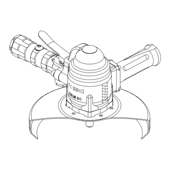
54V Series
Vertical Grinders
Rated Speed/Wheel Capacity
• 4500 - 927 : 4500 RPM w/ 9 Inch T27 Wheel Guard
• 4500 - 928 : 4500 RPM w/ 9 Inch T28 Wheel Guard
• 6000 - 727 : 6000 RPM w/ 7 Inch T27 Wheel Guard
• 6000 - 728 : 6000 RPM w/ 7 Inch T28 Wheel Guard
• 6000 - 927 : 6000 RPM w/ 9 Inch T27 Wheel Guard
• 6000 - 928 : 6000 RPM w/ 9 Inch T28 Wheel Guard
• 8000 - 727 : 8000 RPM w/ 7 Inch T27 Wheel Guard
• 8000 - 728 : 8000 RPM w/ 7 Inch T28 Wheel Guard
Advertisement

Related Manuals for TOP CAT 54VL

Summary of Contents for TOP CAT 54VL
- Page 1 Switch • 8000 - 728 : 8000 RPM w/ 7 Inch T28 Wheel Guard Top Cat ® Air Tools, Manufactured by T.C. Service Co. 38285 Pelton Road, Willoughby, OH 44094 U.S.A. Ph: (440) 954-7500 or (800) 321-6876 ● Fax: (440) 954-7118 or (877) 800-3589...
- Page 2 Operators Instructions and Safety Precautions This is meant to highlight sections of safety standards published by the American National Standards Institute and the Occupational Safety and Health Administration. This is not meant to replace those standards but only highlight certain areas. When care is taken to ensure that the right tool is operated properly, and safety and maintenance procedures are followed, accidents can be avoided.
-
Page 3: Safety In Operation
Proper mounting of grinding Disconnect the tool from the air wheels and inserted tooling supply before doing any service. is crucial to safe operation This prevents accidental start- and efficient working ups. Do not disassemble or adjust conditions. Ensure the the governor. -
Page 4: Maintenance
Maintenance Disassemble 1. Disconnect tool from air supply and remove all wheels and accessories. 2. Secure tool in a vise with motor axis in horizontal position. Clap onto the dead handle (550-1C) of grinder. 3. Remove four screws (700-47A), four lock washers (700-46) and wheel guard (700-200, 700-201 or 412988). 4. - Page 5 Assembly 1. Be sure all parts are clean and free of any abrasive. 2. Press front bearing (700-7) into front bearing support (550-1-BTB). 3. Slip bearing cover (550-25) into front bearing support and onto front bearing. 4. Install snap ring (550-21) into groove of front bearing support with use of snap ring pliers. 5.
- Page 6 Tool Parts Listing TOOLS PART NUMBER DESCRIPTION PART NUMBER DESCRIPTION 400-44 CYLINDER PIN 1100-200 2” WRENCH 550-1-BTB BEARING SUPPORT 1100-650 SPINDLE HOLDER 550-1-C DEAD HANDLE 1100-808 700-9 BEARING DRIVER 550-1-C-H HOLLOWED DEAD HANDLE 1100-825 GOVERNOR WRENCH 550-1-C-KN KNURLED DEAD HANDLE 1100-834 700-7 BEARING DRIVER 550-1-C-KN-W...
- Page 7 Handle Parts Listing PART NUMBER DESCRIPTION 200-9 THROTTLE VALVE O-RING 400-33P OILER PLUG 400-37 SET SCREW 550-30 OPERATING BUTTON 550-30M MACHINE MOUNT BUTTON 550-33 ADAPTER CAP 550-33M METRIC ADAPTER CAP 550-38 LEVER 550-50 LEVER PIN 560-13 THROTTLE VALVE ASSY (INCLUDES 200-9) 600-51 THROTTLE VALVE SPRING 650-1A...
- Page 8 Ergonomics - Work Healthy The following suggestions will help reduce or moderate the effects of repetitive work motion and/or extended vibration exposure: 1) Do not over-grip the machine/tool. Use only the force required to maintain control. 2) Keep hands and body dry and warm. (Blood fl ow is important - exercise hands and arms as often as necessary.) 3) Keep wrists as straight as possible.
-
Page 9: Installation And Maintenance Tips
Installation and Maintenance Tips Following the guidelines will help you to ensure the pneumatic tools your company uses are operating and are maintained in the very best of condition. Initial Inspection of a New Tool When a new tool is delivered to your facility, it is important to inspect the tool for any signs of damage that may have occurred during shipping. - Page 10 Example: Tool rated at 6000 R.P.M. 90% of 6000 (.90 x 6000) = 5400 95% of 6000 (.95 x 6000) = 5700 The tool should run between 5400 and 5700 when tested with a tachometer. Mounting Abrasives The mounting of the abrasive used with the tool is very important to ensure safety for the operator and proper functioning of the tool.
- Page 11 A regulator adjusts the operating pressure supplied to the tool. This device generally is used with a pressure gauge that will indicate the current pressure setting. All Top Cat ® pneumatic tools are designed to operate at 90 PSI (6.2 bar) while the tool is running. The tool should never be run if the pressure should exceed 90 PSI (6.2 bar).
-
Page 12: Air Motors
2) Direct injection of oil into the tool A simple and easy way to ensure proper lubrication is to inject the oil directly into the tool air inlet. This should be performed prior to storage of the tool. To perform this task one must have a small container of the proper lubricating oil.
Need help?
Do you have a question about the 54VL and is the answer not in the manual?
Questions and answers