
Related Manuals for quhwa VP-820A ID


Summary of Contents for quhwa VP-820A ID
- Page 1 Instruction Manual □ VP-720A ID □ VP-820A ID VIDEO DOOR PHONE WITH ID UNLOCK FUNCTION FOR VILLA...
-
Page 2: Table Of Contents
CONTENT PAGE 1. Features 2. Outdoor Camera Performance Data 3. Indoor Monitor Performance Data 4. Indoor Monitor Installation 5. Outdoor Camera Installation 6. Notices of Wiring Diagram 7. Operation Instruction 8. Accessories 9. Notices... -
Page 3: Features
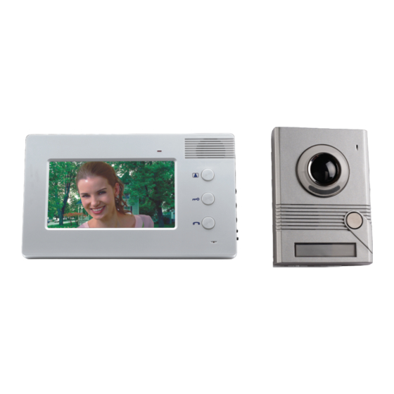
1.Features 1. VP-720A ID indoor monitor is super slim, with only 18.5mm thickness; VP-820A ID indoor monitor uses 8' digital TFT screen with clear images to ensure the best photo quality; Gloss surface; Ipod white and piano black colours available. -
Page 4: Indoor Monitor Performance Data
Unlock Talk Talk Microphone Microphone VP-720A ID Indoor Monitor VP-820A ID Indoor Monitor 1. Adapter input voltage: AC110-120V/60Hz or AC220V-240V/50Hz 2. Adapter output voltage, output current: DC15V 1200mA 22.0mm 18.5mm 3. Talking last time: 120S±10% 4. Monitoring last time: 40S±10% 5. -
Page 5: Indoor Monitor Installation
4.Indoor Monitor Installation Bracket 1. Fix the bracket of the video indoor monitor on the wall with screws (Picture 1). 2. Hang the monitor on the bracket after finishing the wire connection. Plug the enclosed adapter into the sockets and connect the monitor (Picture 2). 5.Outdoor Camera Installation 30.0CM 1. -
Page 6: Notices Of Wiring Diagram
4. Fix the bracket of the outdoor camera on the wall by tightening screws, and then fix the screws at the bottom of the outdoor camera (Picture 3). 6.Notices of Wiring Diagram The video door phone kit includes 15 meters wire. If wanting extension to 15-50 meters, please use the 5×0.75mm wire;... - Page 7 2. VP-720A ID/820A ID Indoor Camera Electronic Control Lock Wiring Diagram 1 Audio Wire 2. Ground Wire 3. Video Wire 4. Power Wire 7. ID Card Function Wire . . . Lock Outdoor Camera Indoor Monitor 1. The 1,2,3,4,7 connection terminals of the outdoor camera connect to the 1,2,3,4,5 connection terminals of the indoor camera accordingly.
- Page 8 3. VP-720A ID/820A ID Outdoor Camera Electronic Control Lock Wiring Diagram 1 Audio Wire 2. Ground Wire 3. Video Wire 4. Power Wire 7. ID Card Function Wire (optional) . . . Lock Outdoor Camera Indoor Monitor A ..
- Page 9 4. VP-720A ID/820A ID Outdoor Camera Electronic Control Lock Wiring Diagram 1 Audio Wire 2. Ground Wire 3. Video Wire 4. Power Wire 7. ID Card Function Wire (optional) 1 2 3 4 5 6 7 Lock Lock Outdoor Camera A Outdoor Camera B (optional) .
-
Page 10: Operation Instruction
7.Operation Instruction 1. Press CALL button of outdoor camera and graceful rings will be heard from indoor monitor as well as images of visitors will be seen. Then you can talk. The talking time can last about 120 seconds. 2. Press TALK button after pressing MONITOR button to monitor the outside and talk with visitors. -
Page 11: Accessories
Thirdly, use the delete card to touch the same area. Then the user card is deleted successfully. 9.3. The adding card and delete card are set well already. If the user loses the adding card or delete card, he or she can re-program a new setting by doing the following steps: Firstly, open the back cover of outdoor station.
Need help?
Do you have a question about the VP-820A ID and is the answer not in the manual?
Questions and answers