Advertisement
Instructions for use and installation
GB
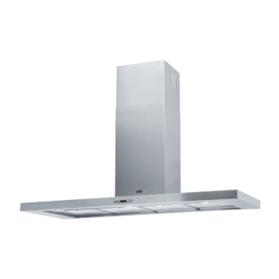
Cooker Hood
Istruzioni per l'uso e l'installazione
IT
Cappa
Mode d'emploi et installation
FR
Hotte de Cuisine
Bedienungsanleitung und Einrichtung
DE
Dunstabzugshaube
Kullanım ve montaj talimatları
TR
Davlumbaz
Uživatelská Pøíruèka
CZ
Odsavač par
FDF 9174
FDF 12174
Advertisement
Table of Contents

Related Manuals for Franke FDF 9174


Summary of Contents for Franke FDF 9174
- Page 1 Instructions for use and installation Cooker Hood Istruzioni per l’uso e l’installazione Cappa Mode d’emploi et installation Hotte de Cuisine Bedienungsanleitung und Einrichtung Dunstabzugshaube Kullanım ve montaj talimatları Davlumbaz Uživatelská Pøíruèka Odsavač par FDF 9174 FDF 12174...
- Page 2 INDEX RECOMMENDATIONS AND SUGGESTIONS ........................3 CHARACTERISTICS ................................4 INSTALLATION..................................5 USE ......................................8 MAINTENANCE ..................................9 INDICE CONSIGLI E SUGGERIMENTI............................11 CARATTERISTICHE................................12 INSTALLAZIONE ................................. 13 USO...................................... 16 MANUTENZIONE ................................17 SOMMAIRE CONSEILS ET SUGGESTIONS............................19 CARACTERISTIQUES................................. 20 INSTALLATION..................................21 UTILISATION ..................................
-
Page 3: Recommendations And Suggestions
RECOMMENDATIONS AND SUGGESTIONS The Instructions for Use apply to several versions of this appliance. Accord- ingly, you may find descriptions of individual features that do not apply to your specific appliance. INSTALLATION • The manufacturer will not be held liable for any damages resulting from in- correct or improper installation. - Page 4 CHARACTERISTICS Dimensions 598-698-898-1198 Min. Min. 650mm 500mm Components 14.1 Ref. Q.ty Product Components Hood Body, complete with: Controls, Light, Blower, 12a 7.2.1 Filters Telescopic Chimney comprising: Upper Section Lower Section Reducer Flange ø 150-120 mm 14.1 Air Outlet Connection Extension Air Outlet Connection Ref.
-
Page 5: Installation
INSTALLATION Wall drilling and bracket fixing 7.2.1 Wall marking: • Draw a vertical line on the supporting wall up to the ceiling, or as high as practical, at the centre of the area in which the hood will be installed. •... - Page 6 Mounting the hood body • Before attaching the hood body, tighten the two screws Vr lo- cated on the hood body mounting points. • Hook the hood body onto the screws 12a. • Fully tighten the support screws 12a. • Adjust the screws Vr to level the hood body. Connections DUCTED VERSION AIR EXHAUST SYSTEM When installing the ducted version, connect the hood to the...
-
Page 7: Electrical Connection
ELECTRICAL CONNECTION • Connect the hood to the mains through a two-pole switch hav- ing a contact gap of at least 3 mm. • Remove the grease filters (see paragraph Maintenance) being sure that the connector of the feeding cable is correctly inserted in the socket placed on the side of the fan. -
Page 8: Control Board
Control board Function Display Switches the extractor motor on and off at the Indicates the selected speed. latest selected speed Decreases the suction speed. Increases the suction speed. By pressing this key it is possible to activate HI appears. The spot down on the right side the intensive speed from any previously se- flashes once a second. -
Page 9: Maintenance
MAINTENANCE Metal grease filters Filters can be washed in the dish machine. They need to be washed when FF-sign appears on the display or in any case every 2 months, or even more frequently in case of particularly inten- sive use of the hood. Alarm reset •... -
Page 10: Charcoal Filter (Recycling Version)
Charcoal filter (recycling version) • This filter cannot be washed or regenerated. It must be replaced when the EF appears on the display or at least once every 4 months. Activation of the alarm signal • In the recycling version hoods the filter saturation alarm must be activated during the instal- lation or later. - Page 11 Franke S.p.a. Via Pignolini,2 37019 Peschiera del Garda (VR) www.franke.it 436003385_ver6...
Need help?
Do you have a question about the FDF 9174 and is the answer not in the manual?
Questions and answers