Table of Contents
Advertisement
Versatile Plus 48'' & 54" Snowblower
ALL TERRAIN VEHICLES & UTILITY VEHICLES
Prestige 54'
and
READ & FOLLOW ALL SAFETY RULES & INSTRUCTIONS BEFORE
106617_en
BERCO
* ASSEMBLY
* OPERATION
CAUTION:
OPERATING YOUR EQUIPMENT
*106180*
OWNER'S MANUAL
Model Number
ALL TERRAIN VEHICLES
for
* REPAIR PARTS
* MAINTENANCE
1
(Original version)
700580-1
700582-1
700360-10
for
M-11
Advertisement
Table of Contents

Related Manuals for Berco Versatile Plus 48’’ 700580-1

Summary of Contents for Berco Versatile Plus 48’’ 700580-1
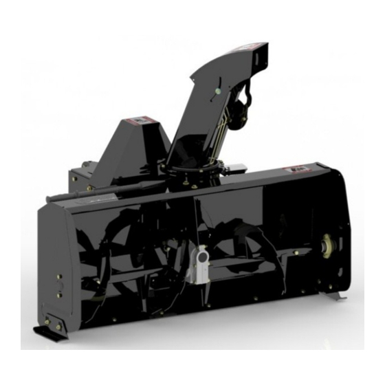
- Page 1 OWNER’S MANUAL (Original version) Model Number 700580-1 700582-1 700360-10 BERCO Versatile Plus 48’’ & 54” Snowblower ALL TERRAIN VEHICLES & UTILITY VEHICLES Prestige 54’ ALL TERRAIN VEHICLES * ASSEMBLY * REPAIR PARTS * OPERATION * MAINTENANCE CAUTION: READ & FOLLOW ALL SAFETY RULES & INSTRUCTIONS BEFORE...
- Page 2 Instructions for Obtaining Warranty Services: Contact the BERCO dealer where equipment was purchased or any other authorized service dealer to arrange service at their dealership. Requests for warranty claims must be carried out through the same distribution network used to purchase the product.
-
Page 3: Table Of Contents
TABLE OF CONTENTS PAGE INTRODUCTION ..............................SAFETY PRECAUTIONS ............................SAFETY DECALS ..............................ASSEMBLY Tools Required ............................Installing the Chute ............................Installing the Snowblower Drive System ....................Adjusting the Height of the Engine Support ....................Positioning the Engine ..........................Installing the Guard ............................ Installing the Electromagnetic Clutch ...................... -
Page 4: Introduction
INTRODUCTION TO THE PURCHASER This new accessory was carefully designed to give years of dependable service. This manual has been provided to assist in the safe operation and servicing of your attachment. NOTE: All photographs and illustrations in the manual may not necessarily depict the actual models or attachment, but are intended for reference only and are based on the latest product information available at the time of publication. -
Page 5: Safety Precautions
SAFETY PRECAUTIONS Careful operation is your best insurance against an accident. Read this section carefully before operating the vehicle and accessory. This accessory is capable of amputating hands and feet and throwing objects. Failure to observe the following safety instructions could result in serious injury. All operators, no matter how experienced they may be, should read this and other manuals related to the vehicle and accessory before operating. - Page 6 SAFETY PRECAUTIONS OPERATION: MAINTENANCE AND STORAGE Do not put hands or feet near, under or inside rotating parts. When cleaning, repairing or inspecting the vehicle and accessory, make certain that all moving parts Exercise extreme caution when operating on or have stopped.
-
Page 7: Safety Decals
SAFETY DECALS REPLACE IF DECALS ARE DAMAGED SEE PARTS BREAKDOWN FOR DECAL LOCATION Symbol Description Decal #105126 To avoid serious injury: Keep hands, feet & clothing away from rotating auger while engine is running. Decal #105127 To avoid serious injury: Keep hands out of this discharge chute while engine is running. -
Page 8: Assembly
ASSEMBLY ASSEMBLY INSTRUCTIONS IMPORTANT: UNLESS OTHERWISE SPECIFIED TORQUE ALL BOLTS ACCORDING TO TORQUE SPECIFICATION TABLE (SEE TABLE OF CONTENTS) WHEN STATED: TIGHTEN FIRMLY. REFER TO PARTS BREAKDOWN SECTION FOR PART IDENTIFICATION. IMPORTANT: THE VEHICLE MUST BE EQUIPPED WITH A TOW HITCH BALL OF 1 7/8’’ IN ORDER TO INSTALL THE SNOWBLOWER. -
Page 9: Installing The Chute
ASSEMBLY For a snowblower already equipped NOTE: 3. Insert the two carriage bolts 1/4" n.c. x 1" (item 1) with a motor, please go to section ‘’vehicle inside the chute as shown in figure below. Insert preparation’’. the gear pin (item 2) in the hole on the support (item 3) and insert the support and motor assembly INSTALLING THE CHUTE (item 4) on the carriage bolts. -
Page 10: Adjusting The Height Of The Engine Support
ASSEMBLY ADJUSTING HEIGHT NOTE: An appropriate choice of holes (A or B) will respect a distance of 13 5/8" (321mm) between the ENGINE SUPPORT middle of the engine shaft and the middle of the gear Adjusting the height of the engine support is NOTE: box shaft. -
Page 11: Positioning The Engine
ASSEMBLY ENGINE PREPARATION: POSITIONING THE ENGINE The figure below shows the position of the back right hand hole on the four engines tested. If another CAUTION engine is installed on the snowblower, all you have to do is attach the engine with the right combination of holes to allow an adequate pulley alignment. -
Page 12: Installing The Electromagnetic Clutch
ASSEMBLY ***NOTE: You may need to add a spacer between INSTALLING THE ELECTROMAGNETIC the clutch and the existing spacer or even changing CLUTCH this spacer. This is related to the tolerances of diffe- NOTE: If the position of the electromagnetic clutch is rent components. -
Page 13: Installing The Electrical Wiring
ASSEMBLY INSTALLING THE ELECTRICAL WIRING 3. Locate orange and green wiring of the 106558 and cable going to engine starter and solenoid. Con- Improper installation of the electrical IMPORTANT: nect as illustrated. wiring might cause damage to the snowblower IMPORTANT: This step is essential since it will pre- components. -
Page 14: Installing The Belt
ASSEMBLY INSTALLING THE BELT 3. Secure the tensioner (item 1) with the pin (item 2) 1. Install the belt (item 1) on the clutch pulley groove and hair pin (item 3). (item 2) closest to the engine (item 3) and on the snowblower V pulley (item 4). -
Page 15: Vehicle Preparation
ASSEMBLY CONTROL BOX INSTALLATION. VEHICLE PREPARATION 1. Choose between the two different ways of ASTENING THE SUBFRAME securing the control box support (item 1). Choose one of the three following options as a Option A means of fastening the subframe. Use two hex bolts 1/4"... -
Page 16: Saddle Preparation
ASSEMBLY NOTE: For snowblowers equipped with a control box. SADDLE PREPARATION: NOTE: All the electrical system is already installed connected various snowblower components. Place the saddle assembly on the A.T.V. seat. Place and tie the wire protector in an appropriate place so the wire protector does not interfere with any hot or moving parts Control box... -
Page 17: Preparing The Subframe
ASSEMBLY PREPARING THE SUBFRAME INSTALLING THE ELECTRICAL SUPPLY 1. Assemble the wheel support (item 1) on the Connect wire assembly (104017) to the positive subframe (item 2) with four hex bolts 3/8" x post on the vehicle’s battery. Connect the black 1"... - Page 18 ASSEMBLY 3. Among the three following configurations, choose 5. Drive the vehicle over the subframe, the height of the hitch support. There must be a Place the hitch under the tow hitch ball and make maximum of ground clearance. (Configuration A) sure there is at least 7"...
-
Page 19: Installing On The Vehicle
ASSEMBLY INSTALLING ON THE VEHICLE 1. Place the hitch (item 1) on the tow hitch ball and secure in place with a pin (item 2) and a hair pin (item 3). IMPORTANT Make sure the vehicle never comes into contact with the subframe even when the vehicle’s suspensions are compressed to the maximum. - Page 20 ASSEMBLY 4. Install the snowblower hitch (item 1) on the wheel 2. In the event where the vehicle is equipped with a support (item 2) of the subframe with a pin (item 3) prominent front bumper or tracks, the assembled and hair pin 4mm (item 4).
- Page 21 ASSEMBLY VERIFYING THE ASSEMBLY 6. In the case the winch is not strong enough to lift the snowblower, it is possible to install the lift system as follows: THE LENGTH OF THE SUBFRAME Attach the lift strap (optional) (item 1) to a well When the vehicle is advancing in a straight line, anchored part of the vehicle.
-
Page 22: Operation
OPERATION WARNING WARNING Never touch with your hands or feet the Read the vehicle's owner’s manual carefully. Be snowblower’s fan, auger or the chute because thoroughly familiar with the controls & proper this is the most frequent cause of accidents use of the attachment. -
Page 23: Snowblowing Technique
OPERATION SNOWBLOWING TECHNIQUE When removing snow, do not use the snowblower as a dozer blade to push snow. Allow snowblower to ingest snow at its own speed. If the speed of your A.T.V. is too fast, the snowblower may become overloaded and clogged. -
Page 24: Maintenance
MAINTENANCE WARNING WARNING Before proceeding with any snowblower -Do not attempt to clear clogged chute, auger or maintenance, assembling or dismounting: fan of snow while the snowblower's engine is Apply parking brakes of the vehicle. running. Stop the snowblower engine and remove the -Disengage snowblower. -
Page 25: Lubrication
MAINTENANCE LUBRICATION AUGER SHEAR BOLT REPLACEMENT SUBFRAME WHEELS Grease the wheel’s axles, the fork pivots after every sixteen hours of use. The shear bolts are to be considered a IMPORTANT: Apply oil at all pivot points. preventive measure and not an assured protection. Operator vigilance is required. -
Page 26: Belt Tension Adjustment
MAINTENANCE CAUTION BELT TENSION ADJUSTMENT If the belt becomes too stretched, it is possible to the Never use the snowblower without the belt guard. change the position of the spring on the tensioner. Just move the carriage bolt (item 1), the sleeve (item 2) the flat washer (item 3) and nut (item 4) to position BELT REPLACEMENT B instead of position A. -
Page 27: Replacing The Augers, Fan And / Or Gear Box
MAINTENANCE 6. Loosen the two set screws (item 1) from ball REPLACING THE AUGERS, FAN AND / bearing behind the snowblower (it may be OR THE GEAR BOX necessary to heat the set screw and the center of the bearing around the shaft to soften the To identify the part numbers, refer to the snowblower “Loctite”... -
Page 28: Dismounting & Storage
DISMOUNTING AND STORAGE DISMOUNTING STORAGE 1. Select a level surface, set the parking brake, stop 1. Clean the snowblower and subframe thoroughly. the engine and remove the ignition key to prevent 2. Paint all the parts wear the paint has worn out. accidental starting. - Page 29 ATV & UV SNOWBLOWER TROUBLESHOOTING * Please refer to parts breakdown section for parts identification. PROBLEM POSSIBLE CAUSES CORRECTIVE ACTION Snowblower vibrates or is Damaged pulley Replace pulley abnormally noisy or bouncing. Damaged bearing Replace the bearing Fan or the augers are damaged Remove and straighten or replace the parts Fan or auger bushings are worn Replace with new bushings...
-
Page 30: Troubleshooting
TROUBLESHOOTING * Please refer to parts breakdown section for parts identification. PROBLEM POSSIBLE CAUSES CORRECTIVE ACTION The engine does not The emergency button is pushed down. The emergency button must be pulled up start to start the engine of the snowblower. The electromagnetic clutch is activated Deactivate the electromagnetic clutch. -
Page 31: 48'' Snowblower
PARTS BREAKDOWN 48’’ SNOWBLOWER # 700580-1-SM... -
Page 32: Parts List
PARTS LIST 48’’ SNOWBLOWER # 700580-1-SM Ref. Qty. Part # English description Description française Réf. Qté. Pièce # Frame 48" with safety decals & cutting edge Chassis 48" avec décalques de séc. & racloir 106609 Hitch Attache 106606 Engine support Support moteur 106607 Bender... - Page 33 Écrou de blocage 5/16" n.c. Flat washer 5/16" hole Rondelle plate 5/16" trou Flat washer 3/8" hole Rondelle plate 3/8" trou Flat washer 7/16" hole Rondelle plate 7/16" trou Berco decal Décalque Berco 102471 Decal danger auger Decalque danger vis 105126 Decal danger belts...
-
Page 34: 54'' Snowblower
PARTS BREAKDOWN 54’’ SNOWBLOWER # 700582-1-SM... - Page 35 PARTS LIST 54’’ SNOWBLOWER #700582-1-SM Ref. Qty. Part # English description Description française Réf. Qté. Pièce # Frame 54" with safety decals & cutting edge Chassis 54" avec décalques de séc. & racloir 106615 Hitch Attache 106606 Engine support Support moteur 106607 Bender Tendeur...
- Page 36 Écrou de blocage 5/16" n.c. Flat washer 5/16" hole Rondelle plate 5/16" trou Flat washer 3/8" hole Rondelle plate 3/8" trou Flat washer 7/16" hole Rondelle plate 7/16" trou Berco decal Décalque Berco 102471 Decal danger auger Decalque danger vis 105126 Decal danger belts...
-
Page 37: Chute
PARTS BREAKDOWN CHUTE... - Page 38 PARTS LIST CHUTE Ref. Qty. Part # English description Description française Réf. Qté. Pièce # Chute with decal Goulotte avec décalque 106613 Bracket Support 103971 Reinforcement plate Plaque de renforcement 103972 Spacer Espaceur 103368 Rotation ring Anneau de rotation 106327 Spacer Espaceur 103361...
-
Page 39: Subframe
PARTS BREAKDOWN SUBFRAME... - Page 40 PARTS LIST SUBFRAME Ref. Qty. Part # English description Description française Réf. Qté. Pièce # Subframe Sous-châssis 104957 Wheel support Support de roue 104770 Rear bracket Fixation arrière 104956 Hitch support Support d'attache 104958 Adjustment tube Tube d'ajustement 104959 Hitch Attache 104639 Hitch ball support...
-
Page 41: Snowblower With Kohler 14Hp Motor
PARTS BREAKDOWN 48” OU 54” VERSATILE PLUS SNOWBLOWER WITH 14HP KOHLER ENGINE... - Page 42 PARTS LIST 48’’ OU 54’’ VERSATILE PLUS SNOWBLOWER WITH 14HP KOHLER ENGINE Ref. Qty. Part # English description Description française Réf. Qté. Pièce # Snowblower Souffleuse à neige 700580 (582)-1-SM Kohler Engine 14 hp Moteur Kohler 14 CV 106014 Electric clutch assembly (Hole 1") Embrayage électrique assemblé...
-
Page 43: Snowblower With Kohler 20Hp Motor
PARTS BREAKDOWN 48’’ OU 54’’ VERSATILE PLUS SNOWBLOWER WITH 20HP HONDA ENGINE... - Page 44 PARTS LIST 48’’ OU 54’’ VERSATILE PLUS SNOWBLOWER WITH 20HP HONDA ENGINE Ref. Qty. Part # English description Description française Réf. Qté. Pièce # Snowblower Souffleuse à neige 700580 (582)-1-SM Honda engine 20 Hp with key Moteur Honda 20 CV avec clé 105538 Electric clutch assembly (Hole 1") Embrayage électrique assemblé...
- Page 45 PARTS LIST 48’’ OR 54’’ VERSATILE PLUS SNOWBLOWER WITH 20HP HONDA ENGINE Ref. Qty. Part # English description Description française Réf. Qté. Pièce # 31 Lock washer 1/4" Rondelle de blocage 1/4" 32 Machine screw Pan head no.8 x 32 x 5/8'' Vis mécanique à tête Pan no.8 x 32 x 5/8" 33 Tie wrap 8"...
-
Page 46: Snowblower With Kohler 23Hp Motor
PARTS BREAKDOWN 48’’ OR 54’’ VERSATILE PLUS SNOWBLOWER WITH 23HP KOHLER ENGINE... - Page 47 PARTS LIST 48’’ OR 54’’ VERSATILE PLUS SNOWBLOWER WITH 23HP KOHLER ENGINE Ref. Qty. Part # English description Description française Réf. Qté. Pièce # Snowblower Souffleuse à neige 700580 (582)-1-SM Electric Clutch Assembly (Hole 1 1/8") Embrayage électrique ass. (Alésage 1 1/8") 106179 Tank support Support de réservoir...
- Page 48 PARTS LIST 48’’ OR 54’’ VERSATILE PLUS SNOWBLOWER WITH 23HP KOHLER ENGINE Ref. Qty. Part # English description Description française Réf. Qté. Pièce # 31 Machine screw Pan head no.8 x 32 x 5/8'' Vis mécanique à tête Pan no.8 x 32 x 5/8" 32 Machine screw Pan head no.10 x 32 x 1 1/2'' Vis mécanique tête pan no.10 x 32 x 1 1/2'' 33 Tie wrap 8"...
-
Page 49: 54'' Prestige Snowblower 700360-10
PARTS BREAKDOWN 54’’ PRESTIGE SNOWBLOWER #700360-10... - Page 50 PARTS LIST 54’’ PRESTIGE SNOWBLOWER #700360-10 Ref. Qty. Part # English description Description française Réf. Qté. Pièce # Snowblower 54" Souffleuse à neige 54" 700582-1-SM Electric Clutch Assembly (Hole 1 1/8") Embrayage électrique ass. (Alésage 1 1/8") 106179 Tank support Support de réservoir 104792 Gasoline tank assembly...
- Page 51 PARTS LIST 54’’ PRESTIGE SNOWBLOWER #700360-10 Ref. Qty. Part # English description Description française Réf. Qté. Pièce # 31 Hex. bolt 3/8" n.c. x 2" GR5 Boulon hex. 3/8" n.c. x 2" GR5 32 Carriage bolt 5/16" n.c. x 1 " GR5 Boulon à...
-
Page 52: Parts Explosive View
PARTS BREAKDOWN EXPLOSIVE VIEW... - Page 53 PARTS LIST 105560 - FAN WITH BUSHING - ÉVANTAIL AVEC COUSSINET Ref. Qty. Part # English description Description française Réf. Qté. Pièce # Éventail 103932 Oil lite bushing Coussinet imprégné d'huile 102784 PARTS LIST 106558 - WIRE ASSEMBLY - FILS ASSEMBLÉS Ref.
-
Page 54: Torque Specification Table
TORQUE SPECIFICATION TABLE GENERAL TORQUE SPECIFICATION TABLE USE THE FOLLOWING TORQUES WHEN SPECIAL TORQUES ARE NOT GIVEN NOTE: These values apply to fasteners as received from supplier, dry or when lubricated with normal oil. They do not apply if special graphited or moly disulphide greases or other extreme pressure lubricants are used. This applies to both UNF and UNC threads. -
Page 55: Options
OPTIONS & ACCESSORIES #700524 #700461 #700260 SUPPORT FOR BATTERY EXTENSION AND SNOW DRIFT CUTTER (BATTERY NOT INCLUDED) SIDE WIDENING ANGLES KIT Slices through high snow drifts to facilitate and For ATV or UV Widens the snowblower to 60" increase snow intake. Package of 2. #700473 #700456-1 EXTENSION... - Page 56 WHEN PERFORMANCE & DEPENDABILITY ARE NON NEGOTIABLE ! Bercomac Limitée 92, Fortin North, Adstock, Quebec, Canada, G0N 1S0 WWW.BERCOMAC.COM PRINTED IN CANADA (ORIGINAL NOTICE)
Need help?
Do you have a question about the Versatile Plus 48’’ 700580-1 and is the answer not in the manual?
Questions and answers