Table of Contents
Advertisement
Quick Links
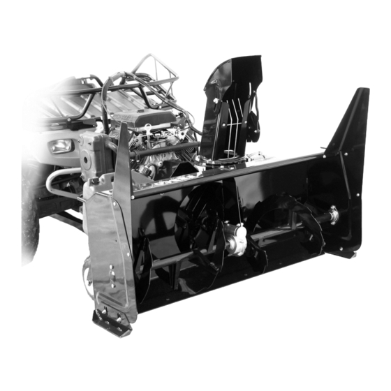
Prestige Two Stage 48" Snowblower
Prestige Two Stage 48" Snowblower
Prestige Two Stage 48" Snowblower
Prestige Two Stage 48" Snowblower
* ASSEMBLY
* OPERATION
READ & FOLLOW ALL SAFETY RULES & INSTRUCTIONS BEFORE
104745
Berco
Berco
Berco
Berco
For
ALL TERRAIN VEHICLES
ALL TERRAIN VEHICLES
ALL TERRAIN VEHICLES
ALL TERRAIN VEHICLES
CAUTION:
CAUTION:
CAUTION:
CAUTION:
OPERATING YOUR EQUIPMENT
OWNER'S MANUAL
OWNER'S MANUAL
OWNER'S MANUAL
OWNER'S MANUAL
Model Number
Model Number
Model Number
Model Number
* REPAIR PARTS
* MAINTENANCE
1
700360- - - - 2 2 2 2
700360
700360
700360
H-08
Advertisement
Table of Contents

Related Manuals for Berco 700360- 700360-2

Summary of Contents for Berco 700360- 700360-2
- Page 1 Model Number Model Number Model Number 700360 700360- - - - 2 2 2 2 700360 700360 Berco Berco Berco Berco Prestige Two Stage 48" Snowblower Prestige Two Stage 48" Snowblower Prestige Two Stage 48" Snowblower Prestige Two Stage 48" Snowblower...
- Page 2 Warranty service is available by returning the "Northeast" snowblower to the authorized dealers. COMMERCIAL OR RENTAL USE: Warranty on BERCO Northeast snowblower used for commercial or rental purposes is limited to 90 days. This warranty does NOT cover: * Wear items, such as shear bolts and belts...
-
Page 3: Table Of Contents
TABLE OF CONTENTS PAGE INTRODUCTION ..............................SAFETY PRECAUTIONS ............................SAFETY DECALS ..............................ASSEMBLY Step 1: Bracket Installation ........................Step 2: Snowblower Preparation ......................Attaching Plate Adjustment ......................Installing Winch Cable ......................... Verify Skid Shoe Adjustment ....................... Step 3: Engine Preparation ........................Saddle Preparation ........................ -
Page 4: Introduction
INTRODUCTION TO THE PURCHASER This new attachment was carefully designed to give years of dependable service. This manual has been provided to assist in the safe operation and servicing of your attachment. NOTE: All photographs and illustrations in the manual may not necessarily depict the actual models or attachment, but are intended for reference only and are based on the latest product information available at the time of publication. -
Page 5: Safety Precautions
SAFETY PRECAUTIONS Careful operation is your best insurance against an accident. Read this section carefully before operating the A.T.V. and snowblower. This snowblower is capable of amputating hands and feet and throwing objects. Failure to observe the following safety instructions could result in serious injury. All operators, no matter how experienced they may be, should read this and other manuals related to the A.T.V. - Page 6 SAFETY PRECAUTIONS 16.Use only accessories approved 4. If the unit should start to vibrate abnormally, stop the manufacturer of the snowblower (such as wheel engine (motor) and check immediately for the cause. chains, and the like). Vibration is generally a warning of trouble. 17.Never operate the snowblower without good 5.
-
Page 7: Safety Decals
SAFETY DECALS REPLACE IF DECALS ARE DAMAGED SEE PARTS BREAKDOWN FOR DECAL LOCATION Decal # 102126 Decal # 103951 Decal # 102125 Decal # 102127... -
Page 8: Assembly
ASSEMBLY IMPORTANT: TORQUE ALL BOLTS ACCORDING TO TORQUE SPECIFICATION TABLE (SEE TABLE CONTENTS) WHEN STATED: TIGHTEN FIRMLY. REFER PARTS BREAKDOWN SECTION FOR PART IDENTIFICATION. Overall view STEP 1 BRACKET INSTALLATION: You must obtain the brackets available through ‘’BOMBARDIER’’ or ‘’WARN’’. Please see instructions included with brackets. -
Page 9: Step 2: Snowblower Preparation
ASSEMBLY STEP 2 SNOWBLOWER PREPARATION: Remove the two 7/16 x 2’’ hex bolts (item 1), the right and left spring links (item 2). Remove bolts and spring links Align the subframe (item 1) under the snowblower and hold in place with the bolts (item 2) you removed and the two 7/16 x 1 1/2’’... - Page 10 ASSEMBLY Insert the wheel support assembly (item 1) into the subframe (item 2). Secure in place with two 3/8 x 2 1/2’’ hex bolt (item 3) and two 3/8’’ flange nuts. Tighten firmly. Install the wheel support assembly Remove the two lock pins (item 2). Carefully drive the ATV over the subframe (item 1) and lift subframe into place on the brackets.
-
Page 11: Attaching Plate Adjustment
ASSEMBLY ATTACHING PLATE ADJUSTMENT: This subframe (item 1) is equipped with two attaching plates (item 2). These plates are adjustable to accommodate different A.T.V.s with or without cat tracks. Adjust these plates for different lengths INSTALLING THE WINCH CABLE Remove the two hair pins (item 1). Pull the winch hook over the small pulley (item 2). -
Page 12: Step 3: Engine Preparation
ASSEMBLY STEP 3 ENGINE PREPARATION: CAUTION Oil must be added to this motor. Please refer motor’s owner’s manual instructions and proper winter oil recommendations. Connecting the wire assembly: The kit is equipped with a connector which will permit you to remove the snowblower quickly without having to remove the wiring. -
Page 13: Operation
OPERATION OPERATING THE SNOWBLOWER WARNING You must be sitting on the saddle in order to start the snowblower engine. Read the A.T.V.’s owner’s manual carefully. Be thoroughly familiar with the controls & proper a) Make sure the snowblower is clear of snow use of the attachment. -
Page 14: Maintenance
MAINTENANCE AUGER SHEAR BOLT WARNING REPLACEMENT *Shear bolts are to be considered a preventive TO PREVENT INJURIES: measure and not a assured protection. Operator Stop the snowblower motor. vigilance is required. Thoroughly inspect the areas Apply parking brake. where the snowblower is to be used and remove all Remove the ignition key. -
Page 15: Belt Replacement & Adjustments
BELT REPLACEMENT & ADJUSTMENTS BELT REPLACEMENT: TIMING BELT ADJUSTMENT: For belt part numbers, refer to snowblower parts breakdown section for parts identification To obtain the right tension on the timing belt, make Snowblower must be detached & disconnected sure that the four nuts (item 7) are loosened. Tighten from the A.T.V. -
Page 16: Troubleshooting
TROUBLESHOOTING PROBLEM POSSIBLE CAUSES CORRECTIVE ACTION Snowblower vibrates Damaged pulley. Replace pulley. abnormally noisy. Damaged bearing. Replace bearing. Damaged fan. Dismount & repair or replace fan. One or both sections of the auger is Replace one or both sections of bent. - Page 17 TROUBLESHOOTING PROBLEM POSSIBLE CAUSES CORRECTIVE ACTION The chute plugs easily. Snowblower engine is turning too Always have engine at full R.P.M. slowly. when using the snowblower. Advancing too quickly with A.T.V. Reduce speed. Allow snowblower to ingest snow at its own speed. Snowblower digs into ground.
-
Page 18: Rotation System With Chute
PARTS BREAKDOWN / NOMENCLATURE DES PIÈCES ROTATION SYSTEM WITH CHUTE SYSTÈME DE ROTATION AVEC GOULOTTE... - Page 19 PARTS LIST / LISTE DES PIÈCES Ref. English description Description française Qty. Part # Réf. Qté. Pièce # 1 Chute Goulotte 103936 2 Bracket Support 103971 3 Reinforcement plate Plaque de renforcement 103972 4 Spacer Espaceur 103368 5 Rotation ring Anneau de rotation 103974 6 Hex.
-
Page 20: Saddle Assembly
PARTS BREAKDOWN / NOMENCLATURE DES PIÈCES SADDLE ASSEMBLY / SELLE ASSEMBLÉE... - Page 21 PARTS LIST / LISTE DES PIÈCES Ref. English description Description française Qty. Part # Réf. Qté. Pièce # 1 Seat cover Couvre-siège 103987 2 Control board Tableau de contrôle 104011 3 Switch support Support de commutateur 104012 4 Safety switch ass'y Commutateur de sécurité...
-
Page 22: Snowblower
PARTS BREAKDOWN / NOMENCLATURE DES PIÈCES SNOWBLOWER / SOUFFLEUSE... - Page 23 PARTS LIST / LISTE DES PIÈCES Ref. English description Description française Qty. Part # Réf. Qté. Pièce # 1 Frame 48" Châssis 48" 103954 2 Gear box 48" Boîte d'engrenage 48" 103948 3 Reduction plate Plaque de réduction 103959 4 Shaft Arbre 103961 5 Key 1/4"...
- Page 24 PARTS LIST / LISTE DES PIÈCES Ref. English description Description française Qty. Part # Réf. Qté. Pièce # 31 Flange nut 3/8" n.c. Écrou à bride 3/8" n.c. 32 Fan Éventail 103932 33 Shear plate Plaque de cisaillement 103933 34 Shear bolt / N.I.L.N. (auger) pkg-10 Boulon de séc.
- Page 25 72 Warning decal Décalque attention 102125 73 Serial number Numéro de série 74 Berco decal Décalque Berco 102471 75 Machine screw P.H. #10 x 32 x 1 1/2" Vis mécanique P.H. #10 x 32 x 1 1/2" 76 Lock washer 7/16"...
-
Page 26: Subframe
PARTS BREAKDOWN / NOMENCLATURE DES PIÈCES SUBFRAME / SOUS-CHÂSSIS... - Page 27 PARTS LIST / LISTE DES PIÈCES Ref. English description Description française Qty. Part # Réf. Qté. Pièce # 1 Subframe Sous-châssis 103989 2 Push frame Châssis de poussée 103982 3 Wheel support Support de roue 103984 4 Pin Goupille 103958 5 Hair pin 3mm Goupille à...
- Page 28 PARTS LIST / LISTE DES PIÈCES Ref. Qty. Part # English description Description française Réf. Qté. Pièce # 31 Flange nut 3/8" n.c. Écrou à bride 3/8" n.c. 32 Nylon insert lock nut 5/16" n.c. Écrou à garniture de nylon 5/16" n.c. 33 Hex.
-
Page 29: Torque Specification Table
TORQUE SPECIFICATION TABLE GENERAL TORQUE SPECIFICATION TABLE USE THE FOLLOWING TORQUES WHEN SPECIAL TORQUES ARE NOT GIVEN NOTE: These values apply to fasteners as received from supplier, dry or when lubricated with normal oil. They do not apply if special graphited or moly disulphide greases or other extreme pressure lubricants are used. This applies to both UNF and UNC threads.
Need help?
Do you have a question about the 700360- 700360-2 and is the answer not in the manual?
Questions and answers