
Related Manuals for ELAC Navigation Echosounder LAZ 5100

Summary of Contents for ELAC Navigation Echosounder LAZ 5100
- Page 1 communications ELAC Nautik NAVIGATION ECHOSOUNDER LAZ 5100 Technical Handbook TH 52 603 8001 E...
- Page 2 ELAC Nautik NAVIGATION ECHOSOUNDER LAZ 5100 Technical Handbook TH 52 603 8001 E Edition: February 2003 L-3 Communications ELAC Nautik GmbH Neufeldtstraße D-24118 Kiel, Germany Telephone: ++49 431 883 - 0 Telefax: ++49 431 883 496 Email: marketing@elac-nautik.com / support@elac-nautik.com http:\\www.elac-nautik.com...
- Page 3 Offenders will be held liable for the payment of damages. All rights reserved in the event of the grant of a patent, utility model or design. © L-3 Communications ELAC Nautik GmbH, Kiel, 2003 Page I L-3 ELAC Nautik...
- Page 4 Declaration of Conformity Page II L-3 ELAC Nautik...
- Page 5 EG- Baumusterprüfbescheinigung Page III L-3 ELAC Nautik...
- Page 6 EG- Baumusterprüfbescheinigung Page IV L-3 ELAC Nautik...
- Page 7 EG- Baumusterprüfbescheinigung Page V L-3 ELAC Nautik...
- Page 8 EG- Baumusterprüfbescheinigung Page VI L-3 ELAC Nautik...
-
Page 9: Table Of Contents
Chapter Title GENERAL FUNDAMENTAL SAFETY INSTRUCTIONS GENERAL INSTALLATION INSTRUCTION FOR ECHOSOUNDERS TRANSDUCER INSTALLATION 2.1.1 CABLE LENGTH, OPERATING FREQUENCY 2.1.2 CABLING, CABLE LOCATION, CABLE SPECIFICATION 2.1.3 TRANSDUCER CABLE SPECIFICATION 2.1.4 INTERFACES 2.1.5 INSTALLATION REPORT; SERVICE REQUEST TECHNICAL DESCRIPTION GENERAL SYSTEM CONFIGURATION 3.2.1 DISPLAY AND CONTROL UNIT 3.2.2... - Page 10 4.4.1 GAIN, RANGE AND DIM SETTINGS 4.4.2 GENERAL INFORMATION REGARDING MENUS 4.4.3 ALTERING SYSTEM SETTINGS/PARAMETERS WITHIN A MENU MENU DESCRIPTION 4.5.1 THE ALARM MENU 4.5.2 THE PARAMETER MENU 4.5.3 THE LOG DATA MENU 4.5.4 THE SYSTEM SET-UP MENU INSTALLATION, CARE AND MAINTENANCE INSTALLATION 5.1.1 DISTORTION LEVEL TEST...
-
Page 11: General
GENERAL FUNDAMENTAL SAFETY INSTRUCTIONS General remark to hydroacoustic equipment LAZ 5100 Even with a carefully selected transducer position and proper installation, the function of hydroacoustic equipment can be impaired by turbulence, acoustic noise or aerated water. As main causes, the following can be stated: −... - Page 12 Work on the system must only be carried out by a qualified technician or a specially trained person working under the supervision of such a technician. Electrical engineering regulations must be observed at all times. Observe all safety instructions and warnings for operating and maintenance attached to the system.
-
Page 13: General Installation Instruction For Echosounders
GENERAL INSTALLATION INSTRUCTION FOR ECHOSOUNDERS TRANSDUCER INSTALLATION The performance of an echosounder is limited by the acoustical propagation of sound in water. Mainly this is influenced by the transducer mounting place, the operational frequency and the transducer efficiency. The transducer mounting place is to select in such a way, that the transducer surface is free of air bubbles and turbulence. - Page 14 Table of maximum measurable water depth, depending on frequency, transducer type, cable length. Transducer Frequency Manufacturer Type LSE 132 30 kHz LSE 297 50 kHz LSE 133 50 kHz SW 6016 100 kHz LSE 148 100 kHz LSE 313 200 kHz LSE 135 200 kHz The depth values can only be reached with limited cable length and an undisturbed...
-
Page 15: Cabling, Cable Location, Cable Specification
2.1.2 CABLING, CABLE LOCATION, CABLE SPECIFICATION Critical point in cabling is the correct handling of the cable screens, especially for the transducer cable. The cable screens have to be grounded only at one point: at the echosounder. In all connection boxes the screens are slide and not connected to ground. Dismantling has to be as short as possible. -
Page 16: Installation Report; Service Request
2.1.5 INSTALLATION REPORT; SERVICE REQUEST After the installation and the quick check ( see chapter 5.1.2) are completed, please fill in the installation report and send a copy to the ELAC Nautik service center ( FAX +49 431 883 366 ). The original belongs into the technical handbook. - Page 17 Installation – Report Schiffsname Ship’s name Installationsfirma Installation Company Installationsdatum Date of Installation LAZ 5100 Werk-Nr. (S/N) Serial Number Wandlertyp Transducer Type Digitale Tochteranzeige Digital Display Unit Einstellungen LAZ 5100 Settings Frequenz / Frequency Blocking Depth Draft Trim Location NMEA - Interface Baudrate Mode Repetition Rate...
- Page 18 Service – Anforderung / Service Request LAZ 5100 ES 5000 Schiffsname: Ship’s Name: ___________________ Item Menu „Alarm“ Alarm Alarm depth Alarm Alarm depth Menu „Parameter“ Sound velocity Units Depth mode Menu „System Set Up“ Date, Time Service 3.2.1 Channel Settings 3.2.1.1 Draft 3.2.1.2 Trim 3.2.1.4 Blocking Depth...
-
Page 19: Technical Description
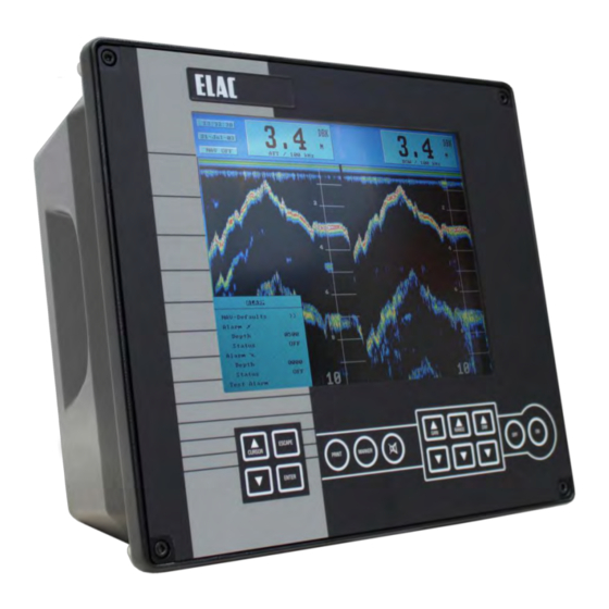
TECHNICAL DESCRIPTION GENERAL The LAZ 5100 Navigation Echosounder is a compact, processor controlled, state of the art system. Presentation of the water depth is made on a Liquid Crystal COLOR Display (LCD) as. • depth below the keel (DBK) Logically structured MENUS assist the user when selecting the operating parameters required. Built to the highest standards, it is certified to meet all requirements laid down by the IMO Resolution MSC 74/69: Amendments to Resolution A.224,Annex 4 . -
Page 20: System Configuration
SYSTEM CONFIGURATION NOTE: See also Figure 3-2, System Configuration with Options. The basic system configuration is as follows: • 1 x Display and Control Unit LAZ 5100 • 1 x Connection Box • 1 x Transducer 3.2.1 DISPLAY AND CONTROL UNIT The Display and Control Unit will normally be installed on the bridge, either mounted in a console or bracket mounted to the deckhead or bulkhead. -
Page 21: Transducer Connection Box
3.2.2 TRANSDUCER CONNECTION BOX This will usually be installed near the transducer, to allow a defective transducer to be replaced without having to replace the complete cabling to the Display and Control Unit. The connection box must be made of metallic material. 3.2.3 TRANSDUCER The transducer converts electrical energy to sound energy and transmits this towards the sea bed. - Page 22 NAVIGATIONS- ECHO SOUNDER MAINS OPTIONAL SWITCH BOX OPTIONAL 2nd TRANSDUCER CONNECTION BOX TRANSDUCER Figure 3-2 : System Block Diagram with Options Operator´s Fitness Check Mute- Control, TXD1 for Voyage Data Recorder ( NMEA, RS 422) LAZ 5100 NMEA RS 422 RS 232 RS 422 MAINS...
-
Page 23: Digital Slave Display(S)
3.3.1 DIGITAL SLAVE DISPLAY(S) These are used to repeat water depth information at other parts of the ship where such information is needed. A total of two Digital Slave Displays can be connected directly to the system. NOTE: Echosounding Systems and remote indicators which detect and display the water depth from a single momentary value per transmission pulse, e.g. -
Page 24: Transducer Options
3.3.4 TRANSDUCER OPTIONS If a 2 channel module is installed, the system is capable of accommodating two transducers without further modification, e.g. one fore and one aft, one port and one starboard. Information received from either or both transducer(s) can be called up for display. 3.3.5 SWITCH BOX If no 2 channel module is installed, a switch box can be used for the connection of two transducers... -
Page 25: Technical Data
TECHNICAL DATA Supply voltage, nominal Power consumption Operating temperature range Storage temperature Housing Protection code Transducer impedance Pulse length Measurement ranges Auto range Digital Depth Information Resolution Measuring accuracy Display Display size Pixels Minimum sounding depth Depth corrections Starting with software version 1.82 Standard frequencies (kHz) 2 Channel version Output power... - Page 26 Deadman alarm Power alarm : altering parameters of the unit causes an output to a central alarm unit ( potential free relais contact ) : when the power supply voltages decreases 100 V a visual and audio alarm ( with mute control ) is activated, a potential free output for external use is available ( potential free relais contact ) L-3 ELAC Nautik...
-
Page 27: Electromagnetic Compatibility
3.4.1 ELECTROMAGNETIC COMPATIBILITY The LAZ 5100 conforms with specifications laid down in DIN * EN 60945 (IEC945+A1) Navigation equipment for Shipping; all editions up to March 1997 and also to the newest version 4 with measurements up to 2 GHz. A declaration of conformity, in accordance with European Community guideline 89/336/EG, can be found in Figure 3-4 on page 3-17. -
Page 28: Interfaces
INTERFACES The LAZ 5100 has the following interfaces: • RS 422, NMEA, for Navigation data input (X4), Blanking input • RS 232, Personal Computer connection for testing (X5) • Centronics, parallel Printer connection (X7) • RS 422, Digital Slave Display connection and potential free relay contacts for alarm ACTIVE (X8), relay control for Operator´s Fitness Check •... -
Page 29: Description Of Nmea Interfaces
3.5.1 DESCRIPTION OF NMEA INTERFACES All serial interfaces described in this chapter conform to EN 61162-1 ( 2001 ). (X4) A navigation system can be connected to this interface so that the ship's co-ordinates are displayed by the LAZ 5100. The system will accept and evaluate data sentences in NMEA 0183, Version 2.30, GLL and ZDA formats, as follows: GLL Format $--GLL IIII.II,a yyyyy.yy,a hhmmss.ss A hh... - Page 30 Example: $ZAZDA 184533.20 20,12,1995 12,15 62 (X8) Interface for START/ STOP - SLAVE indicator, potential free alarm relay contacts and Digital Slave Indicator. After each sounding the LAZ 5100 transmits depth information to the Digital Slave Display interface (15 to 60 times per minute, depending upon the measuring range selected) in NMEA, Version 2.00 format.
- Page 31 Example: $SDDPT 0337.0 -1.5 ,0500,*4D<CR><LF> Depth Below Transducer (DBT) $SDDBT x.x,f x.x,M x.x,F hh Example: $SDDBT 0012.1,f 0003.7,M 0002.0,F 32 <CR><LF> <CR><LF> L-3 ELAC Nautik Checksum Range Scale Transducer=1.5 metres above the keel Depth in metres Checksum Depth in fathoms Depth in metres Depth in feet Checksum...
- Page 32 A NMEA proprietary sentence ELAC is available to allow the transfer of dual channel depth information, including transducer mounting position. ELA (Manufacture’s Mnemonic Code) CSDS, , k x.x d.d -t.t m g S= Starboard, P= Port, B= Bow, A= Aft, 0=not selected K=DBK (Depth below Keel), S=DBS (Depth below Surface), T=DBT (Depth below Transducer) Range Scale...
-
Page 33: Other Interfaces
3.5.2 OTHER INTERFACES (X5) Reserved for service technicians for testing purposes and transferring data to a PC (special software required). (X6) This interface provides a power supply and serial Data output for a second Digital Slave Display and a blanking pulse output. (X7) This Centronics interface allows an EPSON LX 300 (or compatible) printer to be connected to the system. - Page 34 NMEA IN CANL*** SioBRxD+ Sio0RxD n.c. Sio0TxD Blanking in - n.c. Blanking in + Ground CANH*** n.c. SioBRxD- n.c. n.c. n.c. n.c. LEGEND: nc = not connected --- = not available * Blanking + : open Collector (Potentialfree Transistor output ) Blanking - : open Emitter ** Relays;...
- Page 35 EC- Approval Figure 3-4 : Copy of the Original Declaration of Conformity Page 3-17 L-3 ELAC Nautik...
-
Page 36: Operating Instructions
OPERATING INSTRUCTIONS SWITCHING THE SYSTEM ON/OFF ESCAPE CURSOR ENTER To switch the System ON, press the far right-hand key marked "ON". The system will switch ON and assume the parameter settings which were selected when the system was last switched OFF. To switch the system OFF, press and hold the second key from the right, marked "OFF", the system will switch OFF after about 3 to 5 seconds. - Page 37 ESCAPE CURSOR ENTER • GAIN : The GAIN keys are used to alter the system gain, otherwise known as amplification, to achieve a clearer presentation. The system can be operated with either automatic or manual gain control. See chapter 4.4.1. •...
-
Page 38: Display Area
DISPLAY AREA 4.3.1 SINGLE CHANNEL DISPLAY The Display Area is used to present the user with all relevant information. The screen is divided into two areas. The lower, main area is used to present an echogram of the scenario beneath the ship. - Page 39 REPLAY : When the user chooses to display information stored over the previous 24 operating hours (using the LOG DATA MENU), the word "REPLAY" will appear here. The large window at the right-hand side of the information area is used to display the actual water depth, the measurement mode, units of measurement.
-
Page 40: Channel Display
4.3.2 2 CHANNEL DISPLAY In the 2 channel mode information of the transducer location and frequency of the transducer in use is added. If the presentation channel 1/2 is selected, Information of both channels are shown in a vertical split display. The indication NAV OFF is activated without flashing to indicate, that all parameters are mode of presentation is non standard. -
Page 41: Warning Fields
4.3.3 WARNING FIELDS Three warning fields are provided on the display: • NAV OFF flashing indicates that one or more parameters do not correspond to the navigational mode, i.e. the user has selected other units, sound velocity or depth mode. •... -
Page 42: Altering System Parameters And Settings
ALTERING SYSTEM PARAMETERS AND SETTINGS When the system is switched OFF, parameters selected are stored in the system's memory. When the system is switched ON again, these parameters will be retrieved and used (see NOTE below). NOTE: The "DIM" setting is not stored, a pre-set default setting is used when the system is switched ON. - Page 43 RANGE: The RANGE can be set to suit the circumstances e.g. if a water depth of 35 m is indicated, the 50m range will give a better resolution and accuracy than the 200 m range. The range can be altered in the same way as the gain, except that here, pressing the RANGE key will decrease the range and pressing the RANGE key will increase the range.
-
Page 44: General Information Regarding Menus
4.4.2 GENERAL INFORMATION REGARDING MENUS The ENTER key is used to call up the various MENUS in sequence. The order in which they appear is as follows: • Press the ENTER key 1x - ALARM MENU • Press the ENTER key 2x - PARAMETER MENU •... -
Page 45: Altering System Settings/Parameters Within A Menu
4.4.3 ALTERING SYSTEM SETTINGS/PARAMETERS WITHIN A MENU When a MENU is called up, it will appear at the bottom left-hand side of the display area. There are 4 main MENUS available. These can be called up by pressing the ENTER key. Example: The user wishes to change the MINIMUM DEPTH ALARM from 30m to 20m and activate it (Status = ON) and to change the MAXIMUM DEPTH ALARM to 410m... - Page 46 Now press the ENTER key. The cursor will jump from the word "Depth" to the first digit of the alarm setting, in this case a zero. Press the ENTER key twice more and the cursor will move to the right and mark the figure 3, as shown in the MENU below.
- Page 47 Press the ENTER key and the cursor will jump to the word "OFF". Press a CURSOR key ) to toggle from OFF to ON. The MENU will appear as below. Press the ENTER key to confirm the setting. The cursor will jump to the word "Depth" as shown in the MENU below.
- Page 48 Press the ENTER key and the cursor will jump to the first digit of the alarm setting, in this case a 1, as shown in the MENU below. Change the 1 to a 0 by pressing the CURSOR will jump to the next digit, a 9. Repeatedly press the CURSOR reached, in this case a 6.
- Page 49 NAV-Defaults Alarm Depth Status Alarm Depth Status Test Alarm Press the ENTER key and the cursor will jump to the word "OFF". The MENU will appear as shown overleaf. ALARM >> 0020 0610 L-3 ELAC Nautik Page 4-14...
- Page 50 Alter the Status to ON as described for the minimum depth alarm. Press the ENTER key to confirm. The cursor will jump to the words "Test Alarm", as shown in the MENU below. A functional test of the audio/visual alarm can now be carried out by pressing the ENTER key. The audio alarm must sound and the field(s) showing the alarm setting(s) on the display area must blink.
-
Page 51: Menu Description
MENU DESCRIPTION 4.5.1 THE ALARM MENU To call up the ALARM MENU, press the ENTER key once. This MENU is used to set, select or test the following: • Select NAV-Defaults • Set Minimum Depth Alarm • Set Maximum Depth Alarm •... - Page 52 To set the system back to NAV defaults, call up the ALARM MENU and press the following keys: • CURSOR (1x, to mark NAV-Defaults) • ENTER (1x, to call up SUB-MENU) • CURSOR • ENTER (to confirm selection and exit SUB-MENU) •...
-
Page 53: The Parameter Menu
4.5.2 THE PARAMETER MENU To call up the PARAMETER MENU, press the ENTER key twice. Channel Select Sound Velocity Units Depth Mode Gain The PARAMETER MENU is used to select system parameters which vary from those laid down by the IMO. The following and settings can be made within this MENU: •... - Page 54 Sound Velocity Sound travels at varying speeds in water, depending upon the salinity, temperature and density. The standard NAV(Navigation) default setting for sound velocity is 1500 m/s. If a sound velocity measuring system is available and the user wishes to adjust the sound velocity of the depth sounder, call up the PARAMETERS MENU and press the following keys: •...
- Page 55 • CURSOR (4x, to mark Depth Mode) • ENTER (1x, to mark the mode selected) • CURSOR • ENTER (1x, to confirm selection) • ESCAPE (2x, to leave the MENU) NOTE: When the NAV-Defaults are selected within the ALARM MENU, the system returns to the navigation mode, using the default values , i.e.: •...
-
Page 56: The Log Data Menu
4.5.3 THE LOG DATA MENU To call up the LOG DATA MENU, press the ENTER key three times. The MENU as shown below will appear. LOG DATA View Data Transfer The LOG DATA MENU is used to gain access to data stored in the system's built-in 24 hour ring memory. - Page 57 To view stored data Call up the LOG DATA MENU as described previously. Press the CURSOR the word "VIEW", followed by the ENTER key. The MENU will disappear from the screen and stored data will appear. A typical Viewed Data display area can be seen below. The upper part of the display area contains the following information which is always related to the 1st data block on the extreme right of the display area: •...
- Page 58 Explanation of controls for viewing data direction A CURSOR CURSOR ENTER MARKER PRINT ESCAPE NOTE: With the exception of the DIM and OFF keys, all other keys are inoperative. Reference line for information and setting print out time period limits Function Scrolls forwards in time (direction A) Scrolls backwards in time (direction B)
- Page 59 Scrolling through memory data To scroll the display to a certain time in the memory at which events that occurred earlier (relative to time shown in "time" window) wish to be viewed, press and hold the CURSOR nearing the desired time (shown in the "time" window). Finely adjust the desired time by pressing the CURSOR key momentarily, each time a key is pressed, the time will advance by a 5 second period.
- Page 60 Printing data from the memory In order to make a print-out of all or part of the data stored in the memory, so called "limit markers" must be set. Only data within these limit markers will be printed out. To set these limit markers and print the data within them, proceed as follows: •...
-
Page 61: The System Set-Up Menu
4.5.4 THE SYSTEM SET-UP MENU WARNING: With the exception of the time, date and contrast, no other parameters must be altered unless modifications are made to the system, e.g. altering the installation depth of the transducer, replacing the transducer for one of a different frequency. - Page 62 • ENTER (1x, to confirm selection and jump to the year setting) • CURSOR • ENTER (1x, to confirm selection) • ESCAPE (2x, to leave the MENU) To change the system TIME, call up the SYSTEM SET-UP MENU and press the following keys: •...
- Page 63 COLOR BAR MENU allows user settings according to ambient conditions. Several combinations of echo indication and the overlay of general information are possible according the following table. Example: CC B>R means CC: Colored overlay, Colored echotrace B>R: Blue are week echoes, Red are strong echoes LETTERS OVERLAY Text...
-
Page 64: Installation, Care And Maintenance
INSTALLATION, CARE AND MAINTENANCE INSTALLATION The display and control unit can be panel, bulkhead, deckhead or console mounted. The system is delivered with mounting brackets as specified by the user. Install the display and control unit in accordance with the relevant section of the Installation Drawing Number EZ 52 590 8001 to 8010 which can be found in chapter 6 "DRAWINGS"... - Page 65 Once the transducer has been installed, the system must be set up to take certain factors into consideration. These are: • Never paint the radiating surface of the transducer. • Transducer installation depth beneath the surface. • Transducer installation height relative to the lowest part of the ship's keel. •...
-
Page 66: Distortion Level Test
5.1.1 DISTORTION LEVEL TEST After routing and connecting the transducer cable a distortion level test has to be carried out, to ensure the correct routing and screening of the transducer cables. Test procedure: 1. Switch on the echosounder LAZ 5100 2. - Page 67 Figure 5-1 Instruction for transducer- cable connection L-3 ELAC Nautik Kabelklemmen nur zur Befestigung der Wandlerkabel Cable Clamps only for fixing of Transducer Cables Kabellänge zwischen VK 10 und Wandler max. 30 m Cable Length between VK 10 and Transducer max. 30 m Page 5-4...
- Page 68 Transducer Frequency Type LSE 131 30 kHz LSE 132 30 kHz LSE 297 50 kHz LSE 133 50 kHz SW 6016 100 kHz LSE 148 100 kHz LSE 313 200 kHz LSE 135 200 kHz Electrical Manufacturer Power Elac Nautik 1000 Watt Elac Nautik 450 Watt...
-
Page 69: Initial System Set-Up
5.1.2 INITIAL SYSTEM SET-UP After installation of the LAZ 5100 please follow this procedure for setting into operation the first time. Item Installation check Main supply (X3) Transducer (X1, X2) – cable screening, cable laying Printer (X7) – max. cable length 5 m NMEA –... - Page 70 Once the system has been correctly installed, the initial set-up can be carried out. Call up the SYSTEM SET-UP MENU by pressing the ENTER key four (4) times. When the SYSTEM SET-UP MENU appears on the display area, press the CURSOR Service is highlighted as shown below.
- Page 71 Access to the SERVICE MENU is gained by pressing any CURSOR key. The word NO will change to YES. Press the ENTER key and the SERVICE MENU, shown below, will appear. SERVICE SERVICE SERVICE Channel 1 Channel 1 Channel 1 Channel 2 Channel 2 Channel 2...
- Page 72 The CHANNEL 1 MENU allows the service technician to set the following parameters: • Draft • Trim • Blocking depth • Frequency • Location To alter the Draft setting, press the following keys: • Call up the CHANNEL 1 SUB MENU as described previously •...
- Page 73 • Call up the CHANNEL 1 SUB MENU as described previously • CURSOR (3x, to mark the word Blocking Depth) • ENTER (1x, to mark the 1st digit) • CURSOR • ENTER (1x, to confirm selection and jump to 2nd digit) •...
- Page 74 In order to set or alter the parameters for Channel 2, call up the CHANNEL 2 MENU, as follows: • Call up the SERVICE MENU as previously described • CURSOR (2x, to mark Channel 2) • ENTER (1x, to call up the Channel 1 parameters MENU as seen below) Proceed from here in exactly the same way as described for Channel 1 settings.
- Page 75 To alter the External PC Mode, press the following keys: • Call up the INTERFACES SUB-MENU as described previously • CURSOR (1x, to mark the word Mode) • ENTER (1x, to mark the selected mode) • CURSOR • ENTER (1x, to confirm selection) •...
-
Page 76: Power Adjust
To alter the Protocol, press the following keys: • Call up the INTERFACES SUB-MENU as described previously • CURSOR (6x, to mark the word Protocol) • ENTER (1x, to mark the selected Protocol) • CURSOR • ENTER (1x, to confirm selection) •... - Page 77 Onboard service is done by exchanging PCB´s ( Printed Circuit Boards), a list of spare parts available can be seen overleaf. Order spares from the address below stating part(s) required and ident. number(s). L-3 Communications ELAC Nautik GmbH Neufeldtstrasse 24118 Kiel...
-
Page 78: Spare Parts List
SPARE PARTS LIST Power supply unit... Printed circuit board A3... Fuses (line) F1, F2, T2A... Main board PSE 33... Frontpanel complete... Spare Part L-3 ELAC Nautik Ident. No..06 990 0274 ...52 603 181801 ...06 710 1200 ...57 319 8001 ...52 603 1002 Page 5-15... - Page 79 DRAWINGS Dimensional drawing Installation drawing Circuit diagram: Connection Diagram Cable Joining List : MB 52 603 8001 : MB 54 555 1101 : MB 54 555 8002 to 8004 : MB 54 568 1101 : MB 54 568 8001 : EZ 52 603 8001 : EZ 54 555 8002 to 8004 : EA 54 555 8002 : EZ 54 568 8001...
Need help?
Do you have a question about the Navigation Echosounder LAZ 5100 and is the answer not in the manual?
Questions and answers