Table of Contents
Advertisement
Quick Links
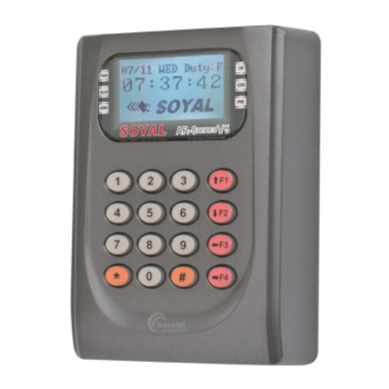
SOYAL
ACCESS CONTROL SYSTEM
Contents
1
Products
2
User Guide
Installation
3
2
4
Notice
1.Tubing:
The communication wires and power line should NOT be bound in the same conduit or tubing.
2.Wire selection:
Use AWG 22-24 Shielded Twist Pair to avoid star wiring ,CAT 5 cable for TCP/IP connection
3.Power supply:
Don't equip reader and lock with the same power supply. The power for reader may be unstable when the lock is activating, that may make the
reader malfunction.
The standard installation: Door relay and lock use the same power supply, and reader use independent power supply.
Connector Table
P7
6
5
4
3
2
1
Cable:
P1
Wire Application
Wire
Lock Relay
1
Blue White (N.O.)DC24V1Amp
2
Purple White (N.C.)DC24V1Amp
Lock Relay COM
3
Door Contact
4
Orange
Exit Switch
5
Alarm Relay
6
Power
7
Thick Red
8
Thick Black DC 0V
Cable:
P2
Wire Application
Wire
Beeper
1
2
LED
3
Door Output
4
Blue White
5
Thin Green Wiegand DAT: 0 Input
Wiegand
6
Thin Blue
WG Door Contact
7
Orange
WG Exit Switch
8
®
3
Terminal Cables
P1
P4
1
P3
P2
P4
8
7
2
7
1
6
6
5
P6
5
4
4
3
4
3
3
2
2
2
1
1
1
P5
3 2 1
8 7 6 5 4 3 2 1
P1
Color
Description
White
(COM)DC24V1Amp
Negative Trigger Input
Purple
Negative Trigger Input
Gray
DC24V1Amp
DC 12V
Color
Description
Pink
Beeper Output 5V/100mA, Low
Yellow
Red LED Output 5V/20mA, Max
Brown
Green LED Output 5V/20mA, Max
Transistor Output Max. 12V/100mA
(Open Collector Active Low)
Wiegand DAT: 1 Input
Negative Trigger Input
Purple
Negative Trigger Input
AR-829E-V5
4
Tools
P2
P3
P5
P6
Use a screwdriver to screw the mounting plate to the wall.
Pull cables ends through the access hole in the mounting plate.
Attach AR-829E to the mounting plate and install screws (supplied) into the
holes at the bottom with the allen key (supplied).
Apply power. LED (green) will light up.
Cable:
P3
Wire Application
TCP/IP Output
Cable:
P4
Wire Application
RS-485 for Lift
Controller
Cable:
P5
Wire Application
Anti-Tamper Switch
Cable:
P6
Wire Application
Power
Security trigger signal
Arming
Duress
Cable:
P7
Wire Application
TTL Port
Copyright © by SOYAL Technology Co., Ltd.. All rights reserved.
5
Optional
AR-821RB
Wire
Color
Description
1
---
---
2
---
---
3
Orange White
Net - TX+
4
Orange
Net - TX-
5
Green White Net - RX+
6
Green
Net - RX-
7
---
---
Wire
Color
Description
1
Thick Green RS-485(B-)
2
Thick Blue
RS-485(A+)
Wire
Color
Description
1
Red
N.C.
2
Orange
COM
3
Yellow
N.O.
Wire
Color
Description
1
Red
DC 12V Output
2
Purple
Security trigger signal Output
3
Red White
Arming Output
4
Yellow White Duress Output
Optional:(Request to purchase AR-725L485 additionally)
Wire
Color
Description
1
Black
DC 0V
2
Yellow
TX
3
White
TE
4
Orange
RX
5
Red
DC 5V
6
---
---
V120508
AR-721RB
Digital Relay
Advertisement
Table of Contents

Related Manuals for Soyal Control Systems


Summary of Contents for Soyal Control Systems
- Page 1 Thin Green Wiegand DAT: 0 Input Wiegand Thin Blue Wiegand DAT: 1 Input Orange WG Door Contact Orange Negative Trigger Input DC 5V WG Exit Switch Purple Negative Trigger Input Copyright © by SOYAL Technology Co., Ltd.. All rights reserved.
- Page 2 Connect to Electric Strike Connect to Door Contact POWER POWER 12VDC 12VDC Electric Strike Alarm N.O. N.C. N.O. Door Contact Relay Outpot Module N.O. Controller Controller N.C. EXIT POWER POWER 12VDC 12VDC Door Contact Copyright by SOYAL Technology Co., Ltd.. All rights reserved.
- Page 3 Setting up the access mode Access programming mode → User Setting → Access Mode → Input User Address → 0: Invalid; 1: Card ; 2: Card or PIN; 3: Card & PIN Copyright by SOYAL Technology Co., Ltd.. All rights reserved.
- Page 4 → Present the tag to reader Input 4 digits arming PWD → Input 4 digits arming PWD → Access Programming mode Enable: Access programming mode → Quit & Arming Disable: Access programming mode → Quit Copyright by SOYAL Technology Co., Ltd.. All rights reserved.
- Page 5 Access programming mode → Tools → Open TimeZone → Set (00~15) → Time (24 Hours) ; Main Port (0:disable, 1: enable) ; WG Port (0:disable, 1: enable) → Weekday (0:disable, 1: enable) → succeeded Copyright by SOYAL Technology Co., Ltd.. All rights reserved.
- Page 6 LCD Access Controller V120508 Firmware Upgrade Get the upgrade software from SOYAL or our distributor and run “UdpUpdater” software Execute the software The software is within SOYAL CD or Login the SOYAL web to downloads Update the firmware [Please login the SOYAL web to download the new ISP Firmware.] 1.
- Page 7 Web Browser by new IP address. User Password Change the log-in password to lock the IP setting of Ethernet Module. The password composes of 10 characters at most, it can be either A~Z or 0~9. Copyright by SOYAL Technology Co., Ltd.. All rights reserved.
- Page 8 LCD Access Controller V120508 Copyright © by SOYAL Technology Co., Ltd.. All rights reserved.
Need help?
Do you have a question about the Control Systems and is the answer not in the manual?
Questions and answers