Table of Contents
Advertisement
Quick Links
Advertisement
Table of Contents

Related Manuals for ooznest Prusa i3


Summary of Contents for ooznest Prusa i3
- Page 1 Prusa i3 Assembly Instructions Written By Ryan Lock...
-
Page 2: Tools Required
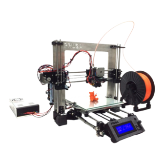
Overview The Prusa i3 is the third iteration in the series of printers designed Josef Prusa, our kit uses his opensource design and adds many beneficial upgrades. Our Kit includes all the parts required to build a Prusa i3 plus many extras that will help you to get printing as quick as possible. - Page 3 Y-Axis Idler Assembly Instructions A)* Insert a M4-Hex-Nut into the inset provided on the backside of the Y-Axis-Idler, screw a M4-20mm-Bolt through the M4-Hex-Nut Nut until it is just about to come through the other side of the M4-Hex-Nut. B) Screw a M3-25mm-Bolt through 2 x 623zz-Flanged Bearings, as in the diagram, insuring that two M3- Washers are included.
- Page 4 Y-Axis Front Assembly Instructions A) Thread M8-Hex-Nuts, M8-Washers, Y-Axis-Idler & Y-Axis-Corner's along the 2 x Threaded-Rod-8mm in the order as shown in the diagram. B) Finger tighten the M8-Hex-Nuts so the Y-Axis-Idler and Y-Axis-Corners are as shown in the left hand image.
- Page 5 Y-Axis Back Assembly Instructions Instructions A) Thread M8-Hex-Nuts, M8-Washers, Y-Axis-Motor & Y-Axis-Corner's along the 2 x Threaded-Rod-8mm in the order as shown in the diagram. B) Finger tighten the M8-Hex-Nuts so the Y-Axis-Idler and Y-Axis-Corners are as shown in the left hand image.
- Page 6 Y-Axis Bed Assembly Instructions A)* Insert M3-Nyloc-Nuts into each of the Hex insets on the 4 Heated-Bed-Spring-Traps. Push a Heated- Bed-Spring-Trap onto each of the corners on the Y-Axis-Bed-Plate B) Attach the Y-Axis-Belt-Holder to the Y-Axis-Bed-Plate using 2 x M3-16mm-Bolts & 2 x M3-Nyloc-Nuts, insure you place a M3-Washer in-between each M3-16mm-Bolt head and the Y-Axis-Belt-Holder, make sure the Y-Axis-Belt-Holder is straight before fully tightening the bolts.
-
Page 7: Y-Axis Assembly
Y-Axis Assembly Instructions A) Thread M10-Hex-Nuts, M10-Washers, M10-Penny-Washers, Y-Axis-Front & Y-Axis-Back on to both Threaded-Rod-10mm in the order as shown in the diagram. B) Insert 2 x Smooth-Rod-350mm through the LM8UU-Bearings of the previously assembled Y-Axis-Bed, then insert the ends of the Smooth-Rod-350mm into the insets on the Y-Axis-Corners, make sure the side on the Y-Axis-Bed with one LM8UU-Bearing is on the left hand side of the assembly. - Page 8 X-Axis Tensioner Assembly Instructions A) Insert A M3-Hex-Nut into the inset provided on the backside of the X-Axis-Tensioner, screw a M3-20mm- Bolt through the M3-Hex-Nut until it is just about to come through the other side of the M3-Hex-Nut. B) Screw a M3-25mm-Bolt through 2 x 623zz-Flanged Bearings, as in the diagram, insuring that two M3- Washers are included.
- Page 9 X-Axis Idler Assembly Instructions A) Insert the X-Axis-Tensioner through the horizontal slot in the X-Axis-Idler as shown above. Screw a M4- 25mm-Bolt through the X-Axis-Idler & X-Axis-Tensioner remembering to include the M4-Washers, then attach a M4-Nyloc-Nut and finger tighten, this will be fully tightened later on once the GT2-Belt has been connected.
-
Page 10: X-Axis Motor Assembly
X-Axis Motor Assembly Instructions A)* Insert a M3-Hex-Nut into the slot provided on the right hand side of the X-Axis-Motor. Screw a M3- 25mm-Bolt through a M3-Washer & Compression Spring, once through the other side attach a M3-Nyloc- Nut to the end. While holding the M3-Nyloc-Nut with a spanner screw the M3-25mm-Bolt until it is flush with the bottom of the M3-Nyloc-Nut. - Page 11 X-Axis Carriage Assembly Instructions A) Insert 4 x LM8UU-Bearings into the bearing holders on the X-Axis-Carriage. Insert a 8mm-Smooth-Rod through each pair of LM8UU-Bearings and securely attach each LM8UU-Bearing to the X-Axis-Carriage using cable ties through the provided slots, the 8mm-Smooth-Rods can now be removed. B)* Push 2 x M3-Nyloc-Nuts into the insets provided.
-
Page 12: X-Axis Assembly
X-Axis Assembly Instructions A) Push a Smooth-Rod-370mm into each hole on the X-Axis-Motor, insure they are fully seated, lightly tap with a hammer if needed. B) Slide the X-Axis-Carriage onto the 2 x Smooth-Rod-370mm, it should be oriented so the teeth on the back of the X-Axis-Carriage are pointing downwards. - Page 13 Attaching Z-Axis Frame Instructions A) Insert the Z-Axis-Frame Between the M10-Penny-Washers on the Y-Axis. B) Adjust the Z-Axis-Frame so the distance between the front side of the Z-Axis-Frame and the end of the Smooth-Rod-350mm is 214mm on both sides. C) Strongly tighten the 4 x M10-Hex-Nuts that are holding the Z-Axis-Frame. Access to these nuts can be improved by removing the Y-Axis-Bed, this can be done by lifting the M8-350mm-Smooth-Rods out of their insets on the Y-Axis-Corner's.
- Page 14 Z-Axis Frame Brace Assembly Part 1 Instructions A) Attach a Z-Axis-Framebrace either side of the Z-Axis-Frame on top of the left hand M10-Penny-Washers. This is done using 4 x M3-25mm-Bolts, 8 x M3-Washers & 4 x M3-Nylocs. The M3-25mm-Bolts go through both Z-Axis-Framebrace's with the M3-Nylocs attaching on the backside.
- Page 15 Z-Axis Frame Brace Assembly Part 2 Instructions A)* Insert a M3-Hex-Nut into each of the 2 slots provided on the Z-Axis-Framebrace. B) Place the Z-Axis-Framebrace-Top over the Threaded-Rod-10mm and tighten down into the inserted M3- Hex-Nut using 2 x M3-20mm-Bolts. C) Repeat the process on the other three Z-Axis-Framebrace's.
- Page 16 Z-Axis Motor Mount Attachment Instructions A) Attach the Z-Axis-Motor-Left using 3 x M3-16mm-Bolts and 3 x M3-Nyloc-Nuts. B) Repeat the process for Z-Axis-Motor-Right. 16 of 61...
- Page 17 Z-Axis Motor Attachment Instructions A) Attach a NEMA17-Stepper-Motor to the Z-Axis-Motor-Left using 3 x M3-12mm-Bolts and 3 x M3- Washers. Make sure that the connection terminal on the NEMA17-Stepper-Motor goes against the frame, and connect the wire that has been pre-inserted through the hole to this terminal. B) Repeat the process to attach the NEMA17-Stepper-Motor to the Z-Axis-Motor-Right.
- Page 18 Z-Axis Nut Traps Assembly Instructions A)* Insert a Brass M5-Hex-Nut in both of the 2 slots on each Z-Axis-Nuttrap, the 2 x M5-Hex-Nuts need to be in sync for the Threaded-Rod-5mm to go through, this has already been done by us, however the procedure to get the 2 x M5-Hex-Nuts in sync is detailed in Appendix B.
- Page 19 Attaching Threaded Rod to Motor Shaft Instructions A)* Insert a M3-Nyloc-Nut into each of the 4 inserts on the Z-Axis-Coupling-Nut-Side. B) Get the previously assembled Threaded-Rod-5mm & Z-Axis-Nuttrap-Left inline with & touching the top of the left hand side NEMA17-Stepper-Motor Shaft. Bring the Z-Axis-Coupling-Nut-Side & Z-Axis-Coupling- Bolt-Side together around the Threaded-Rod-5mm &...
- Page 20 Attaching X-Axis to Z-Axis Instructions A) Slide the previously assembled X-Axis over the 2 x Threaded-Rod-5mm so it sits on top of both Z-Axis- Nuttraps, rotate the Z-Axis-Couplings if necessary to move the respective Z-Axis-Nuttrap up or down. B) Slide down a Smooth-Rod-320mm through both LM8UU-Bearings on the Left & Right side of the X-Axis until it goes into the 8mm hole on the Z-Axis-Motor-Left &...
- Page 21 Z-Axis Top Assembly Instructions A) Insert a 625zz-Bearing into the inset on the Z-Axis-Top-left until it is flush with the top, this may require a tap with a hammer. B) Attach the Z-Axis-Top-Left to the Z-Axis-Frame using 2 x M3-16mm-Bolt & 2 x M3-Nyloc-Nut, before tightening repeat the same procedure with the Z-Axis-Top-Right, then tighten them both fully.
- Page 22 Attaching RAMPS 1.4 Instructions A) Attach a Black Heatsink to each of the 4 x Stepper Drivers on the RAMPS-1.4 Board (Red Circles), this is done by using a square of the provided Double Sided Aluminium Conductive Sticker in between the Heatsink and the Stepper Driver.
- Page 23 Attaching X-Axis Motor Instructions A) Attach a NEMA17-Stepper-Motor to the X-Axis-Motor using 3 x M3-18mm-Bolts, insure the connection terminal on the NEMA17-Stepper-Motor is pointing downwards. B) Push a GT2-Pulley onto the NEMA17-Stepper-Motor Shaft, position it so the grooved section is in the middle of the horizontal gap which goes through the X-Axis-Motor.
- Page 24 Attaching X-Axis GT2 Belt Instructions A) Loop 1metre of GT2-Belt around the GT2-Pulley on the X-Axis-Motor, then over to X-Axis-Idler and loop it around the 623zz-Flanged-Bearings on the X-Axis Tensioner, adjust the lengths so the two free ends of the GT2-Belt meet at the bottom of the X-Axis-Carriage. B) Loop one free end of the GT2-Belt around one the grooved belt holder's on the X-Axis-Carriage so it comes back on to it's self with the teeth facing each other, insure the GT2-Belt is pushed fully into the grooves on the X-Axis-Carriage so it touches the backside, use a small screw driver to help push it in.
- Page 25 Attaching Y-Axis Motor Instructions A) Attach a NEMA17-Stepper-Motor to the Y-Axis-Motor using 3 x M3-12mm-Bolts, insure the connection terminal on the NEMA17-Stepper-Motor is pointing towards the Z-Axis-Frame. B) Push a GT2-Pulley onto the NEMA17-Stepper-Motor Shaft, position it so it is roughly 1.0mm from the motor casing, this will be adjusted later if needed.
- Page 26 Attaching Y-Axis GT2 Belt Instructions A) Loop 1metre of GT2-Belt around the GT2-Pulley on the Y-Axis-Motor, then over to Y-Axis-Idler and loop it around the 623zz- Flanged-Bearings on the Y-Axis-Idler, adjust the lengths so the two free ends of the GT2-Belt meet at the top of the Y-Axis-Belt- Holder.
- Page 27 Attaching Heated Bed Instructions B) To attach the Heated-Bed to the Y-Axis-Bed, in each corner use a M3-30mm-Bolt, M3-Washer, & a Compression-Spring. The Heated-Bed should be orientated so the plain aluminium side is facing upwards with the power wire connections at the front. The easiest way to attach the Heated-Bed, is to first have the Heated-Bed resting on the Y-Axis-Bed with the Compressions-Springs in-between, and the M3-30mm-Bolt through the whole in each corner, there should be a M3-Washer in-between the bolt head and the Heated- Bed in each corner.
- Page 28 Hotend Fan Assembly Instructions A)* Insert a M3-Nyloc-Nut into each slot provided on the left & right side of the Hotend-Fan-Shroud. B) Attach the 25mm-Hotend-Fan to the Hotend-Fan-Shroud using 4 x M3-18mm-Bolts & 4 x M3-Nyloc- Nuts, the 25mm-Hotend-Fan should be orientated so the flat square side is against the Hotend-Fan- Shroud.
- Page 29 Attaching Extruder Mount Instructions A) Attach the Extruder-Mount to the X-Axis-Carriage using 2 x M3-25mm-Bolt's which screw into 2 x M3- Nyloc-Nuts which are on the back side of the X-Axis-Carriage. You will have to start off screwing the 2 x M3-25mm-Bolt's in at an angle, once there is sufficient clearance to straighten them they can then be screwed through with the long side of an Allen key going through the access holes in extruder body directly opposite (Circled in green above).
- Page 30 Attaching Extruder Instructions Amendment Note: It is recommended that you complete Part A on Page 31 Before doing the steps on this page, then continue on as normal. A) Attach the Extruder to the Extruder-Mount by first feeding the Thermistor & Cartridge Heater wires through the hole in the Extruder-Mount where the Hotend will sit.
- Page 31 Attaching Extruder Fan & Extruder Wiring Instructions A) Attach the Extruder-Fan the to Extruder mount so the air flow opening on the Extruder-Fan is pointing towards the gap through the Extruder-Mount which looks on to the Hotend. Secure it with the supplied Philip Screws, the longer of the two goes in the back left hole and the smaller in the front right.
- Page 32 X & Y-Axis Endstop Holders Instructions A) Insert a Mechanical-Endstop into the X-Axis-Endstop-Holder and attach it to the two Smooth-Rods- 370mm on the X-Axis. Use a cable tie going around the bottom Smooth-Rod-370mm and through the slot on X-Axis-Endstop-Holder to secure it roughly 15mm away from the X-Axis-Motor (This may need adjusting later).
- Page 33 Attaching LCD Controller Instructions A) Attach the LCD-Controller to the 2 x Threaded-Rod-8mm on the front of the Y-Axis. B) Use 2 x M3-18mm-Bolt's, 4 x M3-Washers & 2 x M3-Nylocs to secure it to the top Threaded-Rod-8mm. It is a good idea to leave this step until you a full happy with the machine so you can easily get access to the Y-Axis-Idler if needed.
-
Page 34: Notes On Wiring
Notes On Wiring Appendix C is a RAMPS 1.4 Wiring Diagram which shows where every wire should be plugged into, the wires in the diagram are coloured the same as the wires supplied so take care which colour goes where so you get the correct orientation of each wire. - Page 35 Wiring Part 2 Instructions A) Route the wires from the X-Carriage behind the Threaded & Smooth Rod on the left hand side so they meet with the X & Z endstop wires and sit on top of the X-Axis-Motor. All these wires can now be Cable Tied to the Anchor Point on the X-Axis-Motor (Red Circle), insuring there is enough slack for the left and right motion of the X-Carriage and for the Z-Axis Mechanical Endstop to move down roughly a centimetre.
- Page 36 Wiring Part 3 Instructions A) Wire a Plug to the Power Supply as in the RAMPS 1.4 Wiring Diagram, use the provided Mains Cable. Route the wires through the Power Supply Cover before attaching them to the power supply. B) Connect the Power Supply to the RAMPS 1.4 (Red Circle) as in the RAMPS 1.4 Wiring Diagram. use the provided Red &...
- Page 37 RAMPS Cooling Fans Assembly Instructions A) Attach 2 x 40mm-Fans (Fan Sticker Downwards) to the RAMPS-Fans-Holder using 8 x M3-20mm-Bolts & 8 x M3-Nyloc-Nuts. Insure the position where the leads attach to the 40mm-Fans is closest to the hinge. B)* Insert a M3-Nyloc into each of the two insets on the RAMPS-Fans-Bracket. C) Mate the hinges on the RAMPS-Fans-Holder to the hinges on the RAMPS-Fans-Bracket, and secure them together using 1 x M3-25mm-Bolt, 1 x M3-Nyloc-Nut &...
- Page 38 RAMPS Cooling Fans Attachment Instructions A) Attach the left side of the RAMPS-Fans to the RAMPS-1.4 using the already inserted M3-50mm-Bolt in the bottom left corner of the RAMPS-1.4. Use a M3-8mm-Bolt through only the top board of the RAMPS- 1.4 to secure the the right side of the RAMPS-Fans.
- Page 39 Testing & Commissioning Part 1 Note that pre-configured firmware has been uploaded by us to the arduino, however Appendix D explains the procedure if it ever needs to be uploaded again. When first testing your Prusa it is best to do so via a Computer or Laptop rather than the LCD Controller, the software used in the these instructions is PrintRun (Pronterface) which can be downloaded from: http://koti.kapsi.fi/~kliment/printrun/ Once Extracted/Installed, launch PrintRun, it should look similar to the image below.
- Page 40 Testing & Commissioning Part 2 The Z-Axis Mechanical-Endstop works the opposite way round to the X & Y Mechanical- Endstops, when in normal motion the Red LED on the Mechanical- Endstop should be lit. When the Z-Axis travels down the Hotend will rest on the Print Bed preventing it from going down any further, however the Z-Axis-Nuttrap Left &...
- Page 41 Testing & Commissioning Part 3 Before starting the next step attach the Borosilicate Glass Plate to the Heated-Bed using a bulldog clip on the left and right side. The Borosilicate Glass Plate should be orientated so the longest side is going from left to right and it should sit in-between the front and back bolt heads.
- Page 42 Testing & Commissioning Part 4 To check the 2 x RAMPS Fans work enter M106 S255 into the G-Code Viewer (S255 is the power of the Fan and should range from 0-255), the 2 x RAMPS Fans should now work with the air flowing towards the electronics, if they are blowing the wrong way they need to be turned around.
- Page 43 Testing & Commissioning Part 5 To extrude some ABS Filament set the Hotend Temperature to 230°C, the Heated Bed can now be turned off. Place the Filament on the Spool Holder as shown in the right hand image. Cut some 5cm lengths of filament off the spool, these will be used later to make ABS Juice.
- Page 44 Setting Extruder/Hotend Offset When the printer homes the Z-Axis it release the lever on the Mechanical Endstop, however when it release this lever the Nozzle has already been touching the Build Plate for some distance, therefore a firmware offset is needed to compensate for this distance.
- Page 45 Printing - Part 1 To Print a model it first needs to be in .stl file format, then it is sliced and converted into G-Code which can then be put on to the SD Card and printed from the LCD Controller. For a Slicer we recommended using Cura from Ultimaker, Cura can be downloaded from: http://software.ultimaker.com/ Our instruction manual will cover the basic use of Cura in conjunction with our Printer, however it is recommended...
- Page 46 We have created a pre-configured ABS profile for Cura which can be downloaded from the “Documentation & Downloads” Tab on our product page: http://ooznest.co.uk/3D-Printer-Kits/Prusa-i3-Kit Load this Profile into Cura by going to File > Open Profile and select our profile you just downloaded. All the settings in Cura will now have been set to values which will work with our Printer and the ABS Filament supplied.
- Page 47 Printing - Part 3 Advanced Nozzle Orifice: Should always be kept at 0.4mm. Bottom Layer Speed: Keep this really slow to increase adhesion to the print bed. Outer Shell Speed: Reducing this will increase the exterior quality of the prints. Start/End-GCode The main thing to note here is the lines: ;M42 P5 S255 ;Disable For ABS...
- Page 48 Printing - Part 4 With the Print Bed prepared you are now ready to start your first print. Before starting the print it is good practise to reset the printer, this is done by pressing the button below the Fan Extender on the right hand side of the RAMPS 1.4 Board (It is the Blue/Red button in the lower right corner of the RAMPS Board on the RAMPS 1.4 Wiring Diagram).
-
Page 49: Troubleshooting
Troubleshooting The troubleshooting list below will be extended as we get feedback from users of our kit. Problem: When homing the Z-Axis stops before reaching the Print Bed 1) Check by hand that the Z-Axis has a smooth up and down motion, and isn't catching at any points 2) Insure the M3-25mm-Bolt on the X-Axis-Motor is sufficiently pressing the Mechanical-Endstop on the Z-Axis- Nuttrap-Left Problem: When printing the extruder is making a clicking sound... -
Page 50: Appendix A - Parts List
Appendix A – Parts List Electronic Parts 1 x Taurino Classic (Bottom) 1 x RAMPS Fan Extender 1 x RAMPS Shield (Top) 2 x 12V DC 40mm Fans 4 x A4988 Stepper Drivers 1 x 12V 2Pin Wire 4 x Black Heatsinks 4 x Aluminium Stickers 1 x Ceramic Screw Driver 3 x Mechanical Endstop's... -
Page 51: Mechanical Parts
Appendix A – Parts List 2 x 4 Pin Motor Wires 1 x Extruder Fan 3 x 3 Pin End stop Wires 1 x Hotend Fan 2 x 0.5m Black Power Wire 2 x 0.5m Red Power Wire 1 x USB Cable 1 x 3A Plug 1 x 2m Mains Cable Mechanical Parts... - Page 52 Appendix A – Parts List 2 x 1m GT2-Belt 12 x LM8UU-Bearings (4 Labelled Z-Axis-LM8UU) 4 x 623zz-Flanged-Bearings 5 x Compression-Spring 2 x 625zz-Bearings 1 x PTFE Tubing 1 x Pneumatic Coupling Nuts & Bolts 15 x M3-Hex-Nut 60 x M3-Washer 1 x M4-Hex-Nut 2 x M4-Washer 22 x M8-Hex-Nut...
- Page 53 Appendix A – Parts List 75 x M3-Nyloc-Nut 3 x M3-8mm-Bolt 1 x M4-Nyloc-Nut 20 x M3-12mm-Bolt 15 x M3-16mm-Bolt 15 x M3-18mm-Bolt 20 x M3-20mm-Bolt 20 x M3-25mm-Bolt 15 x M3-30mm-Bolt 2 x M3-50mm-Bolt 1 x M4-20mm-Bolt 1 x M4-25mm-Bolt Extras 1 x Borosilicate Build Plate 1 x 10mm Kapton Tape...
- Page 54 Appendix A – Parts List 1 x 250ml Acetone 1 x Extruder Cleaning Kit Plastic Parts (In Order of Use) 1 x Y-Axis-Idler 4 x Y-Axis-Corner 1 x Inserted M4-Hex-Nut 1 x Y-Axis-Motor 4 x Heated-Bed-Spring-Trap 4 x Inserted M3-Nyloc-Nut 1 x Y-Axis-Belt-Holder 3 x Y-Axis-Bearing-Holder 54 of 61...
- Page 55 Appendix A – Parts List 1 x X-Axis-Tensioner 1 x X-Axis-Idler 1 x Inserted M3-Hex-Nut 1 x X-Axis-Motor 1 x X-Axis-Carriage 1 x Inserted M3-Hex-Nut 2 x Inserted M3-Nyloc-Nut 4 x Z-Axis-Framebrace 4 x Z-Axis-Framebrace-Top 8 x Inserted M3-Hex-Nut 1 x Z-Axis-Motor-Left 1 x Z-Axis-Nuttrap-Left 1 x Z-Axis-Motor-Right 2 x Inserted Brass...
- Page 56 Appendix A – Parts List 1 x Z-Axis-Nuttrap-Right 2 x Z-Axis-Coupling-Bolt- 2 x Inserted Brass Side M3-Hex-Nut 2 x Z-Axis-Coupling-Bolt- 1 x Z-Axis-Top-Left Side 8 x Inserted M3-Nyloc-Nut 1 x Z-Axis-Top-Right 1 x Hotend-Fan-Shroud 2 x Inserted M3-Nyloc-Nut 1 x Extruder-Mount 1 x X-Axis-Endstop-Holder 56 of 61...
- Page 57 Appendix A – Parts List 1 x Y-Axis-Endstop-Holder 1 x RAMPS-Holder 1 x RAMPS-Fans-Holder 1 x RAMPS-Fans-Bracket 2 x Inserted M3-Nyloc-Nut 1 x Power-Supply-Cover 1 x Spool Holder 57 of 61...
-
Page 58: Appendix B - Z-Axis Nuttraps
Appendix B – Z-Axis Nuttraps On the Z-Axis-Nuttraps the two Brass M5-Hex-Nuts have to be in sync, otherwise the Threaded-Rod-5mm will not go through both of them. The method to achieve this is trial and error, first insert a M5-Hex-Nut into one of the slots, this will be the fixed nut. Next Insert the second M5-Hex-Nut but mark with a felt-tip which corner is going in first. -
Page 59: Appendix C - Ramps 1.4 Wiring Diagram
Appendix C - RAMPS 1.4 Wiring Diagram 59 of 61... -
Page 60: Appendix D - Uploading Firmware
Do NOT update the software when prompted. Also download and extract the Firmware from the downloads section at the bottom of our product page: http://ooznest.co.uk/3D-Printer-Kits/Prusa-i3-Kit With the printer plugged in via USB, Disconnected in PrintRun and switched off at the power socket open up the Arduino Software. -
Page 61: Appendix E - Lcd Controller Menu Tree
Appendix E – LCD Controller Menu Tree 61 of 61...
Need help?
Do you have a question about the Prusa i3 and is the answer not in the manual?
Questions and answers