
Related Manuals for Ferroli HXA


Summary of Contents for Ferroli HXA
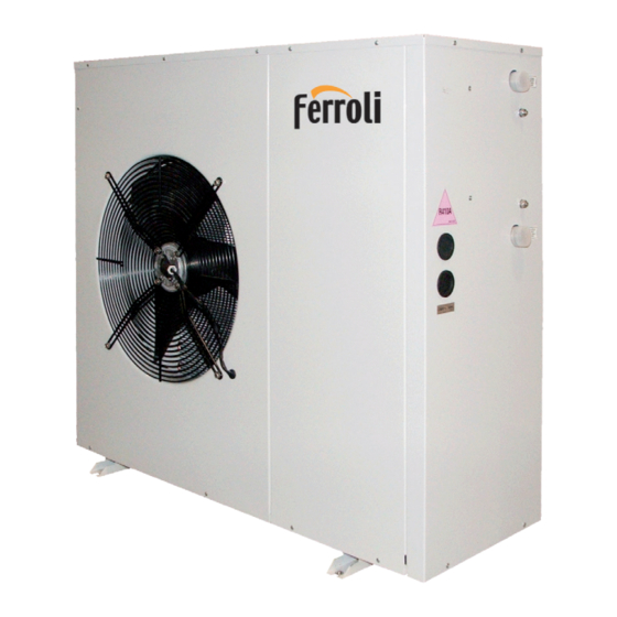
- Page 1 i migliori gradi centigradi AIR - WATER HEAT PUMPS FOR OUTDOOR INSTALLATION INSTALLATION AND OPERATION MANUAL...
- Page 2 Dear Customer, Thank you for having purchased a FERROLI product. It is the result of many years of experiences and of particular research studies and has been made with top quality materials and advanced technologies. The CE mark guarantees that the products satisfy all the applicable European Directives.
-
Page 3: Table Of Contents
TABLE OF CONTENTS GENERAL FEATURES . . . . . . . . . . . . . . . . . . . . . . . . . . . . . . . . . . . . . . . . . . . . . . . . . . . . . . . . . . . . . . . . . . . . . . . . . . . . . . 4 General instructions . -
Page 4: General Features
Maximum absorbed current Refrigerant type and charge weight Unit weight Sound pressure level at 1 metre IP protection level Maximum pressure - high pressure side Maximum pressure - low pressure side PED certification body Ferroli Spa Via Ritonda 78/A (VR) Italy... -
Page 5: Unit Description
GENERAL FEATURES Unit description This series of air-water heat pumps satisfies the heating, coo- The internal programmer clock allows to define different daily ling and domestic hot water production requirements of residen- switching programs for heating, cooling and domestic hot water tial plants of small and medium size. -
Page 6: Description Of Components
GENERAL FEATURES Description of components External structure. Basement, supporting structure and lateral The refrigerant circuit of each unit contains moreover solid panels are made of galvanized and painted sheet-steel (colour core hermetic filter dryer (5) to restrain impurity and moisture residuals that could be present in the circuit, high and low RAL 7035) to guarantee good resistance to atmospheric agents. -
Page 7: Control System
GENERAL FEATURES Control system The microprocessor controller is able to manage not only the unit itself but also all that components of the plant which allow to realize a complete system. The main functions of the control system are : - room temperature control according to the outdoor temperatu- 18:28 re (climatic control) -
Page 8: Options
GENERAL FEATURES Options Standard pump Allows the circulation of the water on the plant side. Plant side Allows the circulation of the water on the plant side and guarantees a higher flow rate High head pump available static head. management Allows the circulation of the water on the plant side and guarantees a high High efficiency pump efficiency. -
Page 9: Accessories
GENERAL FEATURES Accessories Allow to reduce the transmission to the unit support plane of the mechanical vibrations generated by the compressor Rubber vibration dampers and by the fans in their normal operating mode. Coil protection grille Protects the external surface of the finned coil. Allows operating mode selection and set point adjustment. -
Page 10: Technical Data And Performances
TECHNICAL DATA AND PERFORMANCES Technical data Frame 5 .1 6 .1 7 .1 8 .1 10 .1 12 .1 15 .1 18 .1 Model U.M. 230 -1- 50 230 -1- 50 Power supply V-ph-Hz 230 -1- 50 230 -1- 50 230 -1- 50 230 -1- 50 400 -3N- 50... -
Page 11: Nominal Performances - Radiant Plants
TECHNICAL DATA AND PERFORMANCES NOMINAL performances - Radiant plants Frame 5 .1 6 .1 7 .1 8 .1 10 .1 12 .1 15 .1 18 .1 Model U.M. 230 -1- 50 230 -1- 50 Power supply V-ph-Hz 230 -1- 50 230 -1- 50 230 -1- 50 230 -1- 50... -
Page 12: Heating Performances
TECHNICAL DATA AND PERFORMANCES HEATING performances Heating capacity The graphs allow to get the corrective factors to be applied to the nominal performances in order to obtain the real performances in the selected operating conditions. The reference nominal condition is : A7W35 source : air in 7°C d.b. -
Page 13: Cooling Performances
TECHNICAL DATA AND PERFORMANCES COOLING performances Cooling capacity The graphs allow to get the corrective factors to be applied to the nominal performances in order to obtain the real performances in the selected operating conditions. The reference nominal condition is : A35W7 source : air in 35°C d.b. -
Page 14: Plant Side Hydraulic Performances
TECHNICAL DATA AND PERFORMANCES Plant side hydraulic performances Pressure drops - unit without options 12.1 10.1 18.1 15.1 1000 1500 2000 2500 3000 3500 4000 Flow rate [ l/h ] Pressure drops to be added - unit with option “Integrative electrical heaters” 1000 1500 2000... - Page 15 TECHNICAL DATA AND PERFORMANCES Available static head - unit with option “Plant side flow rate management” : “Standard pump” 15.1 18.1 10.1 12.1 1000 1500 2000 2500 3000 3500 4000 Flow rate [ l/h ] Available static head - unit with option “Plant side flow rate management” : “High head pump” 15.1 18.1 10.1...
-
Page 16: Source Side Aeraulic Performances
TECHNICAL DATA AND PERFORMANCES Available static head - unit with option “Plant side flow rate management” : “High efficiency pump” 10.1 12.1 15.1 18.1 1000 1500 2000 2500 3000 3500 4000 Flow rate [ l/h ] The graphs are referred to units operating with water at the temperature of 10°C (density 1000 kg/m... -
Page 17: Operating Limits
TECHNICAL DATA AND PERFORMANCES Operating limits The graphs reported below show the operating area inside which the correct working of the unit is guaranteed. HEATING Inlet air temperature d.b. [°C] COOLING Inlet air temperature d.b. [°C] Temperature difference between unit inlet and outlet Plant side DT max Maximum value... -
Page 18: Electrical Data
TECHNICAL DATA AND PERFORMANCES Electrical data Frame 5 .1 6 .1 7 .1 8 .1 10 .1 12 .1 15 .1 18 .1 Model U.M. Unit Power supply 230-1-50 230-1-50 230-1-50 230-1-50 230-1-50 230-1-50 V-ph-Hz F.L.A. Maximum total current input 10,2 13,4 17,1... -
Page 19: Noise Levels
TECHNICAL DATA AND PERFORMANCES Noise levels Sound pressure level Sound power levels [dB] Sound power by octave bands [Hz] level Model at 1 metre at 5 metres at 10 metres 1000 2000 4000 8000 [dB] [dB(A)] [dB(A)] [dB(A)] [dB(A)] 5 .1 73,6 71,5 69,8... -
Page 20: Weights
TECHNICAL DATA AND PERFORMANCES Weights Frame 5 .1 6 .1 7 .1 8 .1 10 .1 12 .1 15 .1 18 .1 Model U.M. Components weights Unit without options Standard pump Plant side flow rate High head pump management High efficiency pump Integrative electrical heaters Transport weights Unit without options... -
Page 21: Overall Dimensions
TECHNICAL DATA AND PERFORMANCES Overall dimensions Plant return Plant return with option "Plant side water flow management" : "Standard pump" or "High head pump" Plant flow Plant flow with option "Integrative electrical heaters" Frame 1 Frame 2 Frame 3 Pompa Pompa standard alta prevalenza... -
Page 22: Connections
CONNECTIONS Hydraulic connections To design properly the hydraulic system respect the local safety Expansion vessel setting regulations in force. The precharge pressure of the expansion vessel must be It is always necessary to guarantee an appropriate water flow adequate to the total volume of the hydraulic circuit at which the through the plate heat exchanger of the unit even if is installed, unit is connected. -
Page 23: Electrical Connections
CONNECTIONS Electrical connections The electrical wirings must be carried out by qualified personnel Integrative electrical heaters power supply according to the regulations in force at the installation time in the The power supply cables must have an adequate section for the country of installation. -
Page 24: Receiving And Positioning
RECEIVING AND POSITIONING Receiving Check on receiving The unit is supplied on a pallet suitable for the transport. It is As soon as the unit is received verify accurately the correspon- advisable to place protective material between the truck and the dance of the load to what was ordered to make sure that all unit to avoid damages to the unit. -
Page 25: Start Up
START UP Start up The following operations must be carried out only by properly trained personnel. To make the contractual warranty effective, start up must be carried out by authorized service centres. Before calling the service centre it is advisable to make sure that all the installation steps have been completed (positioning, electrical connections, hydraulic connections...). -
Page 26: Control System
CONTROL SYSTEM Control system configuration The control system can be configured in different ways in order to adapt itself to the user needs and to the kind of plant managed Outdoor User air sensor interface by the heat pump. The simpler configuration consists of unit controller (A) and ou- tdoor air temperature sensor (B). -
Page 27: Heating And Cooling Circuits
CONTROL SYSTEM Heating and cooling circuits The controller of the heat pump is able to manage up to two zones : zone 1 : heating and cooling zone 2 : only heating The management of further zones, possibile by means of additional zone controllers, is not treated in this manual. For each zone can be set : set point daily or weekly operating time table... -
Page 28: Control System Devices Installation
CONTROL SYSTEM Control system devices installation REMOTE THERMOSTAT AND REMOTE CONTROL ( WIRED OR WIRELESS ) They should be located in the main room of the zone they manage taking into account the following criteria : the place of installation should be chosen so that the sensor can min. - Page 29 CONTROL SYSTEM OUTDOOR AIR SENSOR The device must be installed outside the building. The sensor is con- nected to the controller of the unit or to the wireless adaptor through a two wire cable ( the wires are interchangeable ). Ø...
-
Page 30: Wireless Devices Connection
CONTROL SYSTEM Wireless devices connection The wireless devices should be located in such a way that the In order to fulfill the connection two stages are necessary. transmission is as interference free as possible. The following Connection establishment : wireless devices are connected to criteria must be observed : the controller of the heat pump. -
Page 31: Control System Use
CONTROL SYSTEM Control system use The remote control (wired or wireless) allows the complete con- Also the remote thermostat contains a temperature sensor to trol of the system permitting to visualize and modify all the ope- measure the room temperature but allows the access to a limited rating parameters of the unit and is equipped with a temperatu- number of functions. - Page 32 CONTROL SYSTEM USER INTERFACE AND REMOTE CONTROL DISPLAY Heating : Comfort set point Heating : Reduced set point Heating : Frost Protection set point Cooling : Comfort set point Wait Xxxxxxxxxxxxxxxxxxxxxxxxxxx Change batteries Xxxxxxxxxxxxxxxxxxxxxxxxxxx Holiday function active Xxxxxxxxxxxxxxxxxxxxxxxxxxx Reference to heating circuit REMOTE THERMOSTAT DISPLAY Alarm message Maintenance messages...
- Page 33 CONTROL SYSTEM DHW button Allows to select the domestic hot water heating mode (indicated by a bar under the corresponding symbol). Domestic hot water heating mode ON domestic hot water temperature controlled according to the set time table protective functions active Domestic hot water heating mode OFF protective functions active Domestic hot water heating mode FORCED...
-
Page 34: Control System Programming
CONTROL SYSTEM Control system programming The settings that can not be modified directly through the buttons of the user interface and of the remote controls are accessible through the programming parameters, grouped inside the various programming menus. The menus concerning functions which are not active are automatically hidden. - Page 35 CONTROL SYSTEM Menu Level Parameter Function Preselection Phase 1 on Phase 1 off Phase 2 on Time table 5 Cooling circuit 1 Phase 2 off Phase 3 on Phase 3 off Default values Start Holidays program Heating circuit 1 Operating level Start Holidays program Heating circuit P...
-
Page 36: Remote Thermostat Programming
CONTROL SYSTEM Remote thermostat programming The configuration parameters of the remote thermo- Parameter Function stat must be set on the device itself. A long press (longer than 3 seconds) on the OC- Remote thermostat used as ru = 1 management heating circuit 1 CUPANCY button allows to enter the Programming ru = 3 management heating circuit P... - Page 37 CONTROL SYSTEM Operating mode selection for heating and cooling circuits Heating circuit 1 : through the Heating button on the remote control Heating circuit P : through the Heating button on the remote thermostat Cooling circuit 1 : through the Cooling button on the remote control or through the parameter 901 Set point setting For each heating circuit 3 set points can be set : Comfort, Reduced and Frost Protecion.
-
Page 38: Inputs And Outputs
CONTROL SYSTEM Inputs and outputs The following table shows the list of the inputs and outputs available on the controller of the heat pump along with the expected use. Some inputs and outputs can be configured in a different way by the user in order to manage other plant components which are not contained inside the heat pump. -
Page 39: Alarms
CONTROL SYSTEM Alarms Alarms activation and reset no more shown on the display. Some of these alarms become The controller is able to perform a complete diagnosis of the unit manual reset alarms if the number of events in an hour exceeds detecting all the operating faults and notifying different alarms. -
Page 40: Controller Technical Data
CONTROL SYSTEM Controller technical data Controller 230 Vac (+10% / -15%) Power supply 50 Hz / 60 Hz max 11 VA Safety class (EN 60730) Degree of protection (EN 60529) IP 00 Operating room temperature (not condensing) -20°C ... 50°C Storing room temperature -20°C ... -
Page 41: Sensors Features
CONTROL SYSTEM Wireless repeater 230 Vac (+10% / -15%) Power supply 50 Hz (+6% / -6%) max 0,5 VA wireless BSB bus Communication frequency 868 MHz Safety class (EN 60730) Degree of protection (EN 60529) IP 20 Operating room temperature (not condensing) 0°C ... -
Page 42: Maintenance
MAINTENANCE Maintenance IMPORTANT. MAKE SURE THE UNIT IS NOT ELECTRICALLY POWERED BEFORE CARRYING OUT ANY CLEANING OR MAIN- TENANCE OPERATION. ALL ORDINARY AND EXTRAORDINARY MAINTENANCE OPERATIONS MUST BE CARRIED OUT BY SPECIALIZED AND AUTHORIZED PERSONNEL, IN ORDER TO ENSURE COMPLIANCE WITH THE CURRENT SAFETY REGU- LATIONS. -
Page 43: Safety And Pollution
SAFETY AND POLLUTION General considerations Accessing the unit The access to the unit must be granted exclusively to qualified personnel trained to operate on this type of units and provided with the necessary protection equipment. Moreover such personnel, to operate, must be authorized by the owner of the unit and recognized by the Manufacturer. - Page 44 SAFETY AND POLLUTION Respiratory tract protection For rescue and for maintenance works in tanks, use self-contained breathing apparatus. The vapours are heavier than air and can cause suffocation, reducing the oxygen available for breathing. Eye protection Total protection glasses. Hand protection Rubber gloves.
- Page 46 The manufacturer declines all responsibility for any inaccuracies in this manual due to printing or typing errors. The reserves the right to modify the products contents in this catalogue without previous notice.
- Page 48 Ferroli spa ¬ 37047 San Bonifacio (Verona) Italy ¬ Via Ritonda 78/A tel. +39.045.6139411 ¬ fax +39.045.6100933 ¬ www.ferroli.it...
Need help?
Do you have a question about the HXA and is the answer not in the manual?
Questions and answers