Table of Contents
Advertisement
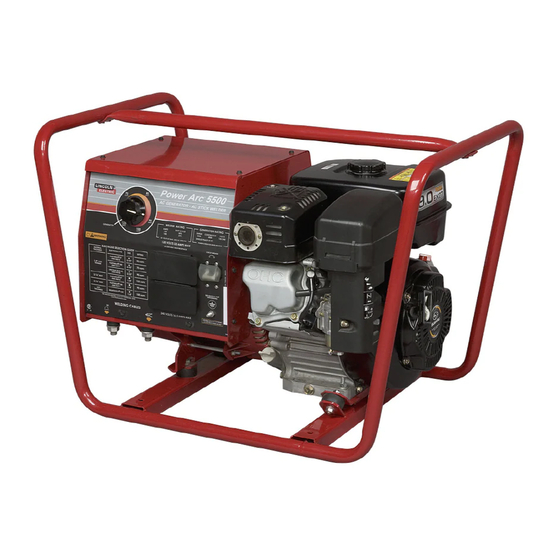
POWER-ARC
This manual covers equipment which is no
longer in production by The Lincoln Electric Co.
Speci cations and availability of optional
features may have changed.
Safety Depends on You
Lincoln arc welding and cutting
equipment is designed and built
with safety in mind. However, your
overall safety can be increased by
proper installation ... and thought-
ful operation on your part. DO
NOT INSTALL, OPERATE OR
REPAIR THIS EQUIPMENT
WITHOUT
READING
MANUAL AND THE SAFETY
PRECAUTIONS CONTAINED
THROUGHOUT. And, most
importantly, think before you act
and be careful.
ISO 9001
ANSI RAB
QMS
Designed and Manufactured Under a
Quality Program Certified by
ABS Quality Evaluations, Inc.
to ISO 9001 Requirements.
CERTIFICATE NUMBER: 30273
• Sales and Service through Subsidiaries and Distributors Worldwide •
Cleveland, Ohio 44117-1199 U.S.A. TEL: 216.481.8100 FAX: 216.486.1751 WEB SITE: www.lincolnelectric.com
For Machines with Code Number 11329, 11405
THIS
Various engine configurations are available and machine appearance will vary
accordingly.
OPERATOR'S MANUAL
• World's Leader in Welding and Cutting Products •
5500
™
Copyright © Lincoln Global Inc.
IM900-A
December, 2008
Advertisement
Table of Contents
Troubleshooting

Related Manuals for Lincoln Electric Power-Arc 5500


Summary of Contents for Lincoln Electric Power-Arc 5500
- Page 1 ™ December, 2008 For Machines with Code Number 11329, 11405 This manual covers equipment which is no longer in production by The Lincoln Electric Co. Speci cations and availability of optional features may have changed. Safety Depends on You Lincoln arc welding and cutting equipment is designed and built with safety in mind.
-
Page 2: Safety
351040, Miami, Florida 33135 or CSA Standard W117.2-1974. A Free copy of “Arc Welding Safety” booklet E205 is available from the Lincoln Electric Company, 22801 St. Clair Avenue, Cleveland, Ohio 44117-1199. BE SURE THAT ALL INSTALLATION, OPERATION, MAINTENANCE AND REPAIR PROCEDURES ARE PERFORMED ONLY BY QUALIFIED INDIVIDUALS. -
Page 3: Electric Shock Can Kill
SAFETY ARC RAYS can burn. ELECTRIC SHOCK can 4.a. Use a shield with the proper filter and cover kill. plates to protect your eyes from sparks and 3.a. The electrode and work (or ground) circuits the rays of the arc when welding or observing are electrically “hot”... - Page 4 SAFETY CYLINDER may explode WELDING and CUTTING SPARKS can if damaged. cause fire or explosion. 7.a. Use only compressed gas cylinders 6.a. Remove fire hazards from the welding area. containing the correct shielding gas for the If this is not possible, cover them to prevent process used and properly operating the welding sparks from starting a fire.
- Page 5 SAFETY 5. Toujours porter des lunettes de sécurité dans la zone de PRÉCAUTIONS DE SÛRETÉ soudage. Utiliser des lunettes avec écrans lateraux dans les zones où lʼon pique le laitier. Pour votre propre protection lire et observer toutes les instruc- tions et les précautions de sûreté...
- Page 6 Electric for advice or information about their use of our products. We respond to our customers based on the best information in our posses- sion at that time. Lincoln Electric is not in a position to warrant or guarantee such advice, and assumes no liability, with respect to such infor- mation or advice.
-
Page 7: Table Of Contents
Welding Operation .....................B-7 Thru B-16 Accessories...........................Section C Maintenance..........................Section D Safety Precautions ..........................D-1 Routine and Periodic Maintenance ....................D-1 General Assembly Exploded View ....................D-5 Troubleshooting and Repair ....................Section E Electrical Diagrams and Dimension Print ................Section F Parts Manual (Robin / Subaru) ..................P-510 Series POWER-ARC 5500... -
Page 8: Installation
INSTALLATION TECHNICAL SPECIFICATIONS - POWER-ARC 5500 K1429-11 INPUT - GASOLINE ENGINE Manufacturer Description Speed Displacement Ignition Capacities Robin / Subaru 1 cyl., 3700 RPM 16.17 cu. in. Manual, Fuel: 1.6 gal. (6.1 l) EX 27 4 cycle ± 50 RPM (265 cc) Recoil start;... -
Page 9: Safety Precautions
INSTALLATION SAFETY PRECAUTIONS LOCATION AND VENTILATION Read this entire installation section before you Whenever you use the POWER-ARC 5500, be sure start installation. that clean cooling air can flow through the machine’s gasoline engine and the generator. Avoid dusty, dirty areas. -
Page 10: Pre-Operation Engine Service
Also, fuel capacity will be a little less at an angle. • Do not leave unattended while LIFTING fueling. The POWER-ARC 5500 should be lifted by two peo- • Wipe up spilled fuel and allow GASOLINE ple. (It weighs 160 lbs/72.5 kg.) Its welded tube roll fumes to clear before starting cage is designed to make lifting easy. - Page 11 Some federal, state, or local laws require spark arresters in locations where unarrested sparks could present a fire hazard. The Power-Arc 5500 is supplied with a spark arrester as standard equipment. Refer to the engine owner’s manual for proper maintenance.
-
Page 12: Electrical Output Connections
INSTALLATION POWER-ARC 5500 OUTPUT CONNECTIONS FIGURE A.1a FOR CODE 11405 FIGURE A.1 FOR CODE 11329 POWER ARC 5500 POWER ARC 5500 POWER ARC 5500 POWER ARC 5500 AMPS AMPS AMPS AMPS AMPS AMPS AMPS AMPS AMPS AMPS AMPS AMPS GENERATOR... -
Page 13: Machine Grounding
1. The gasoline engine must be OFF to install weld- ing cables. When the POWER-ARC 5500 is mounted on a truck 2. Remove the 1/2 - 13 flanged nuts from the output or a trailer, the machine generator terminals. -
Page 14: Premises Wiring
The POWER-ARC 5500 does not have a combined 120/240 volt twist-lock receptacle and cannot be connected to a premises as described in other Lincoln literature. -
Page 15: Electrical Devises Used With The Power -Arc 5500
DO NOT USE THESE DEVICES WITH A POWER-ARC 5500. The Lincoln Electric Company is not responsible for any damage to electrical components improperly connect- ed to the POWER-ARC 5500. POWER-ARC 5500... -
Page 16: Operation
WELDING CAPABILITY • Do not stack anything on or near the The POWER-ARC 5500 is rated 125 amps, 20 volts at 30% engine. duty cycle on a ten-minute basis. This means that you can load the welder to 125 amps for three minutes out of every MOVING PARTS can injure. -
Page 17: Limitations
1. CURRENT CONTROL DIAL: Adjusts continuous LIMITATIONS current output. The amperage on the dial corre- • The POWER-ARC 5500 is not recommended for spond to the average amperage needed for spe- any processes besides those that are normally per- cific Lincoln welding electrodes. -
Page 18: Engine Operation
DO NOT RUN THE ENGINE AT EXCESSIVE SPEEDS. The maximum allowable high idle speed for the POWER-ARC 5500 is 3750 RPM, no load. GASOLINE ENGINE CONTROLS Do NOT adjust the governor screw on the engine. -
Page 19: Before Starting The Engine
Put the “ON/OFF” Switch in the “ON”(I) position. FOR A “COLD” ENGINE: 1. Open the fuel shutoff valve. 2. Place the choke lever in the “CHOKE” position. 3. Pull slightly on the recoil starter handle until resis- tance is felt. POWER-ARC 5500... -
Page 20: Generator Operation
CATIONS, to determine the wattage requirements of the most common types of loads you can power with the POWER-ARC 5500. Be sure to read the notes at BREAK-IN PERIOD the bottom of the table. The engine will use a greater amount of oil during its “break-in”... - Page 21 WATTS = VOLTS X AMPS DRAWN. for example a 120 volt device which is rated on its nameplate to draw 2 amps will need (120 VOLTS) X (2 AMPS) = 240 WATTS OF POWER. 1 KW = 1000 WATTS. POWER-ARC 5500...
-
Page 22: Welding Operation
----------------------------------------------------------- for welding, disconnect the welding cables from the weld output terminals. Reattach the flange The POWER-ARC 5500 has a voltage of up to 62 nuts and leave them on the terminals. Volts AC which can shock. The POWER-ARC 5500... -
Page 23: Welding Guidelines
Semi-automatic, Wire Welding With a Lincoln Wire Feeder / Welder Learning To Stick Weld The Power-Arc 5500 generator power can be used to The serviceability of a product or structure utiliz- supply power up to 4,000 watts continuous input power ing this type of information is and must be the to a Lincoln Wire Feeder/Welder. - Page 24 FIGURE 3 - The welding circuit for (Stick) shielded metal arc welding. FIGURE 3 - The welding circuit for (Stick) shielded metal arc welding. Solidified Slag Shielding Gases Weld Metal Base Metal FIGURE 4 - The welding arc. POWER-ARC 5500...
- Page 25 NOTE: When welding on thin plate, you will find that Correct Welding Position you have to increase the welding speed, whereas when welding on heavy plate, it is necessary to go Figure 5 more slowly to ensure fusion and penetration. POWER-ARC 5500...
- Page 26 (See drawing). channels, angle irons and “I” beams. This type of steel can usually be easily welded without special precautions. Some steel, however, contains higher carbon. Typical applications include wear plates, axles, connecting rods, shafts, plowshares and scraper blades. POWER-ARC 5500...
- Page 27 Vertical-down is used primarily on sheet metal for fast, low penetrating welds. 60° 1/8" (3.2mm) Successive passes must be used to build up butt welds on heavier metal. POWER-ARC 5500...
- Page 28 As soon as it has solidi- fied, the arc is SLOWLY brought back, and another few drops of metal are deposited. DO NOT FOL- LOW THE UP AND DOWN MOVEMENT OF THE ARC WITH YOUR EYES. KEEP THEM ON THE MOLTEN METAL. POWER-ARC 5500...
- Page 29 3. Use low amperage. 75 A for 1/8” (3.2mm) elec- 3. Use 1/8” (3.2mm) Wearshield at 80-100 A. Strike trode, 70 A for 3/32” (2.5mm) electrode. the arc about one inch from the sharp edge. POWER-ARC 5500...
- Page 30 (a), (b) and (c) below. This entire weld on it and the other piece has no weld on it. is especially important on thick castings where maxi- (See drawing below.) mum strength is required. POWER-ARC 5500...
- Page 31 They can be used for repair work when dirt, grease, plating or paint cannot be completely cleaned from the steel. These electrodes are typically used with motions “A” and “B” (see draw- SIDE ing) for the first pass on vertical-up welds. VIEW POWER-ARC 5500...
-
Page 32: Accessories
ACCESSORIES OPTIONS/ACCESSORIES LINCOLN ELECTRIC ACCESSORIES The following options/accessories are available for your POWER-ARC 5500 from your local Lincoln Distributor. Accessory Kit (K875) – Includes the following: • 20 Ft.(6.1m) #6 welding cable with lug. • 15 Ft.(4.6) #6 work cable with lugs. -
Page 33: Maintenance
------------------------------------------------------------- Read the Safety Precautions in the front of this manu- al and in the engine owner’s manual before working on the POWER-ARC 5500. Keep all equipment safety guards, covers, and devices in position and in good repair. Keep your 1. - Page 34 MAINTENANCE FUEL: At the end of each day’s use, refill Clean Rotating Screen: If your POWER-ARC 5500 is the fuel tank to minimize moisture conden- equipped with an engine that has a rotating screen, sation and dirt contamination in the fuel line.
-
Page 35: Engine Maintenance Parts
FIGURE D.5 - SET SPARK PLUG GAP Use the engine owner’s manual for latest Plug Gap Info. CLEAN SPARK ARRESTER SCREEN: Refer to the engine owner’s manual that was shipped with your POWER-ARC 5500 for the proper cleaning instruc- tions. TABLE D.1 ENGINE MAINTENANCE PARTS... - Page 36 MAINTENANCE GENERATOR/WELDER MAINTENANCE RECEPTACLES: Keep the electrical receptacles in good condition. Remove any dirt, oil, or other STORAGE: Store the POWER-ARC 5500 in clean, debris from their surfaces and holes. dry, protected areas. CABLE CONNECTIONS: Check the welding cable CLEANING: Blow out the generator and controls connections at the weld output terminals often.
- Page 37 FIGURE D.6. - MAJOR COMPONENT LOCATIONS 1 . CRADLE ASSEMBLY 2. ROTOR, BLOWER, AND BEARING ASSEMBLY 3. STATOR ASSEMBLY 4. BRUSH AND BRUSH HOLDER ASSEMBLY 5. CONTROL BOX WELDED ASSEMBLY 6. REACTOR ASSEMBLY 7. OUTPUT TERMINAL ASSEMBLY 8. OUTPUT PANEL ASSEMBLY POWER-ARC 5500...
-
Page 38: How To Use Troubleshooting Guide
HOW TO USE TROUBLESHOOTING GUIDE WARNING Service and Repair should only be performed by Lincoln Electric Factory Trained Personnel. Unauthorized repairs performed on this equipment may result in danger to the technician and machine operator and will invalidate your factory warranty. For your safety and to avoid Electrical Shock, please observe all safety notes and precautions detailed throughout this manual. -
Page 39: Troubleshooting
5. Faulty reactor (L1). CAUTION If for any reason you do not understand the test procedures or are unable to perform the tests/repairs safely, contact your Local Lincoln Authorized Field Service Facility for technical troubleshooting assistance before you proceed. POWER-ARC 5500... - Page 40 Authorized Field Service Facility. CAUTION If for any reason you do not understand the test procedures or are unable to perform the tests/repairs safely, contact your Local Lincoln Authorized Field Service Facility for technical troubleshooting assistance before you proceed. POWER-ARC 5500...
- Page 41 Engine is seized and recoil start will not move. CAUTION If for any reason you do not understand the test procedures or are unable to perform the tests/repairs safely, contact your Local Lincoln Authorized Field Service Facility for technical troubleshooting assistance before you proceed. POWER-ARC 5500...
- Page 42 DIAGRAMS POWER-ARC 5500...
- Page 43 DIAGRAMS POWER-ARC 5500...
- Page 44 DIAGRAMS POWER-ARC 5500...
- Page 45 ● ● ● Do not touch electrically live parts or Keep flammable materials away. Wear eye, ear and body protection. WARNING electrode with skin or wet clothing. ● Insulate yourself from work and ground. Spanish ● ● ● No toque las partes o los electrodos Mantenga el material combustible Protéjase los ojos, los oídos y el AVISO DE...
- Page 46 ● ● ● Keep your head out of fumes. Turn power off before servicing. Do not operate with panel open or ● Use ventilation or exhaust to guards off. WARNING remove fumes from breathing zone. Spanish ● Los humos fuera de la zona de res- ●...
- Page 47 • World's Leader in Welding and Cutting Products • • Sales and Service through Subsidiaries and Distributors Worldwide • Cleveland, Ohio 44117-1199 U.S.A. TEL: 216.481.8100 FAX: 216.486.1751 WEB SITE: www.lincolnelectric.com...