Advertisement
BSD – Racing
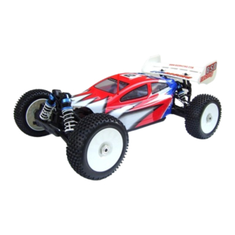
GRANITE MONSTER 1/8 NITRO
NITRO COMPRESSION BUGGY 1/8TH.21 ENGINE
MODEL No: BS802T
Specifications:
Length: 458mm
Width: 305mm
Height: 165mm
Wheelbase: 335mm
Tyre size: 110*43 mm
Ground Clearance: 30mm
Engine: 21#
Instruction Manual
Features:
• Advanced 4WD Drive System.
• Factory Assembled & Ready-to-Run.
• Powerful .21 Nitro Engine.
• 2 Speed Automatic Transmission.
• Oil Filled Dampers.
• 2.4GHz Proportional Radio Control System.
• Quality Bevel Gear Differential.
• 125cc Fuel Tank
IMPORTANT NOTICE
This Century UK- BSD car is very tough, but it is not indestructible. In common with all R/C
cars, stresses and vibrations cancause screws and fastenings to work loose. It is your
responsibility to carry out regular checks, tighten screws where necessary and generally
maintain the car to ensure optimum performance and reliability.
SAFETY PRECAUTIONS
This high performance radio-controlled car is not a toy. Used incorrectly it is capable of
inflicting serious harm to persons or property. It is not recommended for use by children
under 14 years of age unless supervised by a suitably experienced adult.Please read the
contents of this manual prior to operating. If you are uncertain regarding any aspect of its
safe operation please contact your Century UK - BSD dealer to seek help or advice.
www.centuryuk.com
Advertisement
Table of Contents

Subscribe to Our Youtube Channel
Summary of Contents for BSD-Racing BS802T
- Page 1 BSD – Racing GRANITE MONSTER 1/8 NITRO NITRO COMPRESSION BUGGY 1/8TH.21 ENGINE MODEL No: BS802T Specifications: Length: 458mm Width: 305mm Height: 165mm Wheelbase: 335mm Tyre size: 110*43 mm Ground Clearance: 30mm Engine: 21# Instruction Manual Features: • Advanced 4WD Drive System.
- Page 2 Equipment required for operation 1. Tools required for maintenance: WARNING! Do not use a power screwdriver to remove, install or tighten any screws that locate into plastic moulded parts. The high operating speed of these tools may cause the threads in the plastic mouldings to be damaged or stripped.
-
Page 3: Transmitter Specifications
Transmitter Specifications: Channels : 2 Model Type : Car/Boat Frequency : 2.4GHz Power :12V DC (8 x AA batteries) Charging Port : Built-in (centre pole +) Low Voltage Warning : Yes (below 9V) Note: The antenna on the receiver must be positioned vertically to achieve optimum range(Figure 1).It must be kept away from any metallic or carbon components. -
Page 4: Transmitter Functions
Turn Off: 1. Stop the engine. 2. Disconnect the receiver power supply. 3. Turn off the transmitter. Failure to comply with this procedure could result in a total loss of control. Transmitter Functions: DSC FOR SIMULATOR Dual Rate IMPORTANT ALWAYS: Position the car so the wheels are not touching the ground before starting the engine. -
Page 5: Running The Engine
ENGINE TUNING GUIDE MAIN MIXTURE CONTROL NEEDLE The main mixture control needle points upwards from the carburettor (see image). It controls the fuel/air mixture supplied to the engine. The needle is factory set for runningin, at 4 1/2 turns out (anti-clockwise) from its fully closed position. -
Page 6: Break-In Procedure
STOPPING THE ENGINE To stop the engine, pinch the fuel line that runs to the carburettor. Pinching this line will restrict fuel flow and the engine will stop within a few seconds. Never place your finger over the exhaust to stop the engine. This could result in serious burns to your finger and could also cause fuel to “back-up”... -
Page 7: Tuning Tips
FOURTH TANK OF FUEL Lean the main mixture control needle a further ½ turn. Run the car for the tank of fuel and let cool. At this stage you should notice the car is running much smoother and the engine will be producing more power. -
Page 9: Parts List
PARTS LIST Item No. Description Item No. Description BS903-043 Side guard plate-L/R BS905-001 Rear chassis 1pcs BS905-003 Tail wing mount 1pcs BS903-044 Throttle servo mount-A/B BS905-004 Rollcage post set BS903-048 Throttle linkage set BS905-006 Tail wing 1pcs BS903-052 Clutch show w/spring BS905-008 Body front mount/screw BS903-058 Hub rear carrier BS903-003 Shock absorber unit(plastic) 2pcs... - Page 10 PARTS LIST Item No. Description Item No. Description BS936-004 Axle BS903-095 M4*4 set screw 6pcs BS801-002 Engine 21# BS903-096 M4*8 set screw 6pcs BS801-003 Engine washer BS903-097 Diff.gearbox 2pcs BS801-004 Engine crankshaft W/E-Clip BS903-098 Diff.gearbox bulkhead-upper/lower BS801-005 Engine mount BS903-104 Diff.unit BS801-006 Engine flywheel w/pin BS903-105 Driving/driven gear,Diff.gear/bevel BS801-007 Metal pipe...


Need help?
Do you have a question about the BS802T and is the answer not in the manual?
Questions and answers