
Related Manuals for OSC RMX 850

Summary of Contents for OSC RMX 850
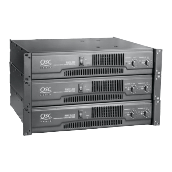
- Page 1 RMX™ Series L L L L L RMX 850 L L L L L RMX 1450 L L L L L RMX 2450 *TD-000078-00* TD-000078-00...
- Page 3 RMX Series Technical Service Manual RMX 850 RMX 1450 RMX 2450 QSC Audio Products, Inc. Technical Services Group Phone: 1-800 QSC AUDIO (1-800-772-2834) USA only +1 (714) 957-7150 Fax: +1 (714) 754-6173 Postal: 1665 MacArthur Blvd. Costa Mesa, California 92626 USA E-mail: tech_support@qscaudio.com...
-
Page 4: Rmx Series Performance Specifications
RMX Series Performance Specifications RMX 850 RMX 1450 RMX 2450 OUTPUT POWER in watts FTC: 20 Hz–20 kHz @ 0.1% THD, both channels driven 8Ω per channel 4Ω per channel EIA: 1 kHz @ 0.1% THD, both channels driven 8Ω per channel 4Ω... -
Page 5: Table Of Contents
7.1 RMX Assembly/Disassembly Diagram 1 of 2 (All models) ....................... 27 7.2 RMX Assembly/Disassembly Diagram 2 of 2 (All models) ....................... 28 7.3 RMX 850 Schematic Diagram 1 of 3 Channel 1 ..........................29 7.4 RMX 850 Schematic Diagram 2 of 3 Channel 2 ..........................30 7.5 RMX 850 Schematic Diagram 3 of 3 Power Supply ......................... -
Page 6: Introduction
1. Introduction 1.1 Service bulletins Contact QSC Technical Services to make sure you have the most up-to-date service bulletins for RMX Series amplifiers. Service bulletins may be distributed in hard copy, via fax, and electronically (Adobe Acrobat PDF) via CD-ROMs, FTP from the QSC web site (www.qscaudio.com), and e-mail. - Page 7 Insertion 1 With a soldering iron and 60/40 or 63/37 eutectic-type solder, melt just enough solder onto one pad to Solder create a small mound (Figure 1.3). 2 Grasp the component in the middle with tweezers. Melt the small mound of solder with the iron and place the component across the two pads (in the correct orientation, if the component is sensitive to Figure 1.3.
-
Page 8: Series Description
The series comprises three models: the RMX 850, RMX Audio circuitry 1450, and RMX 2450. Each one has two audio channels and is two rack spaces tall. -
Page 9: Clip Detection
DC fault. while the negative swings are handled by NPN devices. The The output sections of the RMX 850 and RMX 1450 are AC coupled. collectors all connect to ground, which allows them to be mounted directly to the heat sink—metal-to-metal, without insulators in... -
Page 10: Component Identification And Pinout
Bridged mono operation and protection form a voltage divider between the two channel outputs. If the output signals are mirror images, the voltage at the junction of the When the amplifier is operated in bridged mono, its two channels resistors (bus BR_BAL) will be zero. If the signals are not mirror work in tandem to produce up to twice the voltage swing that a images—for example, one channel is defunct, distorting, or reduced single channel is capable of. - Page 11 2N3904 (NPN) and 2N3906 (PNP) Small-signal IRFZ44 TMOS power field effect transistor transistors B C E MAC224 Triac 2SC5200 (PNP) and 2SA1943 (NPN) Power transistors MJE15032 (NPN) and MJE15033 (PNP) Driver transistors TOSHIBA B C E RMX Series Technical Service Manual...
-
Page 12: Troubleshooting: Symptoms, Causes, & Remedies
3. Troubleshooting: Symptoms, causes, & remedies When first checking the operation of an amplifier on the bench, Slow increase in current draw (current doesn’t become always turn your variable transformer down to zero before plugging excessive until about half of the amplifier’s full AC operating the amplifier in. -
Page 13: Faults With Signal Present
• Base resistors R136 or R137 (Channel 1) or R236 or R237 D216 (Channel 2). (Channel 2) are open. Also check the NTC thermistors R134 • (RMX 850 and RMX 1450) Check R118 and R119 (Channel 1) or (Channel 1) or R234 (Channel 2). R218 and R219 (Channel 2). -
Page 14: Power Supply & Rail Balancing Problems
• When driving a short circuit, the output section’s positive and 3.5 Power supply & rail balancing negative supply rail voltages should be equal, within 3 volts. If problems they aren’t, check D107, D110, R146, and R147 (Channel 1) or D207, D210, R246, and R247 (Channel 2). -
Page 15: Setting Positive And Negative Current Limits
bias, you will need to shut the amplifier off and let it cool down onto one of the brown wires running to the AC switch or onto before you resume. the gray output wire from channel 1's module. Turn the gain control all the way up. Adjust trimpots R139 and Tools and resources you will need: R140 equally until the current measured falls within the range •... -
Page 16: Servicing Rmx Amplifiers
5.1 Mechanical disassembly and re-assembly Replacing components will usually require removing the channel modules and/or AC board from the amplifier chassis, especially on the RMX 850 and RMX 1450, which have single-side printed circuit boards. The RMX 2450 has double-side boards; many of the through-hole components on the upper side of the board can be unsoldered and soldered from the top side of the board, so removing modules or boards is not always necessary. -
Page 17: Replacement Parts
6. Replacement parts 6.1 RMX 850 Replacement Parts QSC part # Description Qty. Notes or Component Reference Misc. 1806-2505-0 POWER TRANSFORMER 700 2113-1144-0 AC INLET 2444-1001-1 KNOB CONTROL 4134-8432-0 RACK-MOUNT BRACKET 5200-4717-0 ROCKER POWER SWITCH 5200-3532-0 CIRCUIT BREAKER 10A For 120V models... - Page 18 Channel 1 module (continued) QSC part # Description Qty. Notes or Component Reference 4860-5050-5 TR 2SC5200 T0-3P (L) Q108, Q110, Q112 4860-5060-5 TR 2SA1943 T0-3P (L) Q103, Q107, Q109 4860-8890-0 TR MPS A06 VCE 80V NS 8910-0062-0 CE 80V 4700U 20% RL 25X C120, C121 8910-0274-0 THERMAL PTC 60C 100 ohm...
- Page 19 Channel 2 module (continued) QSC part # Description Qty. Notes or Component Reference 4860-5030-5 TR MJE15033 Q206 4860-5050-5 TR 2SC5200 T0-3P (L) Q208, Q210, Q212 4860-5060-5 TR 2SA1943 T0-3P (L) Q203, Q207, Q209 8910-0062-0 CE 80V 4700U 20% RL 25X C220, C221 8910-0274-0 THERMAL PTC 60C 100 ohm...
-
Page 20: Rmx 1450 Replacement Parts
6.2 RMX 1450 Replacement Parts QSC part # Description Qty. Notes or Component Reference Misc. 1806-2506-0 POWER TRANSFORMER, 1200 2113-1144-0 AC INLET 4134-9101-0 METAL WIND GUIDE 4154-0361-0 FAN GUIDE 5200-4717-0 ROCKER POWER SWITCH 5200-3531-0 CIRCUIT BREAKER 15A For 120V models 5200-4731-0 CIRCUIT BREAKER 8A For 230V models... - Page 21 Channel 2 module (continued) QSC part # Description Qty. Notes or Component Reference 8910-0274-0 THERMAL PTC 60C 100 ohm 8910-0488-0 ROD THERMISTOR NTC 50ohm R134 Channel 1 SMT parts 150F-222K-6-CF CC 50V 2200pF 10% 1206 1 C115 150H-102J-6-CF CC 100V 0.001U 5% 1206 C114 4720-103J-J RMG 1/10W 10K 5% 0805...
- Page 22 Channel 2 module (continued) QSC part # Description Qty. Notes or Component Reference 8910-0274-0 THERMAL PTC 60C 100 ohm 8910-0488-0 ROD THERMISTOR NTC 50ohm R234 Channel 2 SMT Parts 150F-104K-6-CF CER2 1206 X7R 50V 100N C100, C102, C104 150F-181K-J-BD CC 50V 180P 10% 0805 C101, C103, C201, C203 150F-222K-6-CF CC 50V 2200pF 10% 1206 1...
-
Page 23: Rmx 2450 Replacement Parts
6.3 RMX 2450 Replacement Parts QSC part # Description Qty. Notes or Component Reference Misc. 1806-2507-0 POWER TRANSFORMER, 1800 2113-1144-0 AC INLET 4134-9101-0 METAL WIND GUIDE 4154-0361-0 FAN GUIDE 5200-4717-0 ROCKER POWER SWITCH 5200-3531-0 CIRCUIT BREAKER 15A For 120V models 5200-4731-0 CIRCUIT BREAKER 8A For 230V models... - Page 24 Channel 1 module (continued) QSC part # Description Qty. Notes or Component Reference 4718-153J-2-X RMF 1W 15K 5% AT METAL R165 4718-220J-2-P RMF 1W 22R 5% AT FP R136, R137 4718-3R3J-1-X RMF 1W 3.3R 5% AL R146, R147, R20 4719-1R5J-1-X RMF 2W 1R5 5% AL METAL R181, R182 4719-5R6J-1-X...
- Page 25 Channel 1 module (continued) QSC part # Description Qty. Notes or Component Reference 4720-472J-J RMG 1/10W 4.7K 5% 0805 R114, R138, R174, R179, R187, R193, R214, R238 4720-473J-J RMG 1/10W 47K 5% 0805 R183 4720-474J-J RMG 1/10W 470K 5% 0805 R172, R185 4720-592A-J RMG 1/10W 5.9K 1% 0805...
- Page 26 Channel 2 module (continued) QSC part # Description Qty. Notes or Component Reference 4860-5020-5 TR MJE15032 Q205 4860-5030-5 TR MJE15033 Q206 4860-5050-5 TR 2SC5200 T0-3P (L) Q204, Q208, Q210, Q212 4860-5060-5 TR 2SA1943 T0-3P (L) Q203, Q207, Q209, Q211 4860-5250-5 TR 2N5064 TRIODE D219, D220 4860-8890-0...
-
Page 27: Schematics And Diagrams
THIS DOCUMENT CONTAINS PROPRIETARY REVISIONS 7. Schematics and diagrams INFORMATION WHICH IS THE PROPERTY DESCRIPTION EFF DATE CHK APPROVED DATE OF QSC AUDIO PRODUCTS, THAT MAY NOT BE DISCLOSED, REPRODUCED OR USED WITHOUT EXPRESS WRITTEN CONSENT FROM QSC AUDIO PRODUCTS. SCREW 4 REQD PWR PCB... -
Page 28: Rmx Assembly/Disassembly Diagram 2 Of 2 (All Models)
THIS DOCUMENT CONTAINS PROPRIETARY INFORMATION WHICH IS THE PROPERTY OF QSC AUDIO PRODUCTS, THAT MAY NOT BE DISCLOSED, REPRODUCED OR USED WITHOUT EXPRESS WRITTEN CONSENT FROM QSC AUDIO PRODUCTS. SCREW 5 REQD SCREW 6 REQD KNOB 2 REQD CHASSIS SCREW 4 REQD WIRE ASSY 7.2 RMX Assembly/Disassembly Diagram 2 of 2... -
Page 29: Rmx 850 Schematic Diagram 1 Of 3 Channel 1
PARTS IN COMMON TO BOTH CH: 1-99. CH 1 PARTS 101-199, CH 2 PARTS 201-299. APPROVALS DATE SCHEMATIC DIAGRAM .XXX 7.3 RMX 850 Schematic Diagram 1 of 3 DRAWN 3. COMPONENTS MARKED WITH ARE SAFETY CRITICAL PARTS. DEBURR EDGES .XXX R MAX... -
Page 30: Rmx 850 Schematic Diagram 2 Of 3 Channel 2
SW-GND FOR CLIP LIM 10.0K-1%-1/2W ^R_0805 SEE SH 1 BR_RET BR MONO RETURN -- CAUTION, SENSITIVE NODE Gray shading indicates signal path 7.4 RMX 850 Schematic Diagram 2 of 3 Channel 2 SIZE FSCM NO. DWG NO. SH-000850-00 NOTES: UNLESS OTHERWISE SPECIFIED SCALE CAD FILE NO. -
Page 31: Rmx 850 Schematic Diagram 3 Of 3 Power Supply
J157:1 200V-1A JP10 NEUT 20 VAC TO FAN POWER RECTIFIER 28V PRI-SIDE DC FAN SUPPLY 1.1 AMP 1000-35V 7.5 RMX 850 Schematic Diagram 3 of 3 Power Supply SIZE FSCM NO. DWG NO. SH-000850-00 NOTES: UNLESS OTHERWISE SPECIFIED SCALE CAD FILE NO. -
Page 32: Rmx 1450 Schematic Diagram 1 Of 3 Channel 1
REVISION THIS DOCUMENT CONTAINS PROPRIETARY INFORMATION WHICH IS THE PROPERTY DESCRIPTION EFF. DATE APPROVED / DATE OF QSC AUDIO PRODUCTS, THAT MAY NOT BE DISCLOSED, REPRODUCED OR USED PROTOTYPE RELEASE 3-01-00 WITHOUT EXPRESS WRITTEN CONSENT FROM QSC AUDIO PRODUCTS. CLEAN UP BY PHQ 3-02-00 CLEAN UP BY AA 3-10-00... -
Page 33: Rmx 1450 Schematic Diagram 2 Of 3 Channel 2
THIS DOCUMENT CONTAINS PROPRIETARY INFORMATION WHICH IS THE PROPERTY OF QSC AUDIO PRODUCTS, THAT MAY NOT BE DISCLOSED, REPRODUCED OR USED WITHOUT EXPRESS WRITTEN CONSENT FROM QSC AUDIO PRODUCTS. CHANNEL-2 C201 180p-5% ^C_0805 R205 R228 R229 Q201 +VCC_B R235 +78V 3904 R226 10.0K... -
Page 34: Rmx 1450 Schematic Diagram 3 Of 3 Power Supply
THIS DOCUMENT CONTAINS PROPRIETARY INFORMATION WHICH IS THE PROPERTY OF QSC AUDIO PRODUCTS, THAT MAY NOT BE DISCLOSED, REPRODUCED OR USED WITHOUT EXPRESS WRITTEN CONSENT FROM QSC AUDIO PRODUCTS. RECTIFIERS BR100, 200 AND C127-227 ARE MUTING AND THERMAL PROTECTION. LOCATED OFF THE MAIN PCB, MOUNTED TO CHASSIS. -
Page 35: Rmx 2450 Schematic Diagram 1 Of 3 Channel 1
POS STEP DRIVER THIS DOCUMENT CONTAINS PROPRIETARY +110_A INFORMATION WHICH IS THE PROPERTY C170 OF QSC AUDIO PRODUCTS, THAT MAY NOT BE DISCLOSED, REPRODUCED OR USED 47pF-50V-5% WITHOUT EXPRESS WRITTEN CONSENT FROM Q170 ^Q_BJTN_SOT-23 R170 QSC AUDIO PRODUCTS. ^C_0805 RFZ44 Q171 R172 D171... -
Page 36: Rmx 2450 Schematic Diagram 2 Of 3 Channel 2
THIS DOCUMENT CONTAINS PROPRIETARY INFORMATION WHICH IS THE PROPERTY OF QSC AUDIO PRODUCTS, THAT MAY NOT BE DISCLOSED, REPRODUCED OR USED WITHOUT EXPRESS WRITTEN CONSENT FROM QSC AUDIO PRODUCTS. POS STEP DRIVER +110_B C270 47pF-50V-5% Q270 ^Q_BJTN_SOT-23 R270 ^C_0805 RFZ44 Q271 3904 R272... -
Page 37: Rmx 2450 Schematic Diagram 3 Of 3 Power Supply
THIS DOCUMENT CONTAINS PROPRIETARY INFORMATION WHICH IS THE PROPERTY OF QSC AUDIO PRODUCTS, THAT MAY NOT BE DISCLOSED, REPRODUCED OR USED WITHOUT EXPRESS WRITTEN CONSENT FROM QSC AUDIO PRODUCTS. CT_A SEE SH 1 J104:12 J21:1 RECTIFIER BR100-201 CIRCUIT +14V MUTING AND THERMAL PROTECTION. IS DRAWN FOR CHASSIS MTG E112 +110_A... -
Page 38: Rmx 850 Chassis Wiring Diagram
CIRCUIT- AC POWER BREAKER SWITCH AUDIO PRODUCTS, INC. NEUT PWR PCB JP10 COSTA MESA, CALIFORNIA 1724-340A-0102 WIRING DIAGRAM, RMX 850 7.12 RMX 850 Chassis Wiring Diagram NOTES: UNLESS OTHERWISE SPECIFIED SCALE SHEET NONE 1 OF 1 QSC Audio Products, Inc. -
Page 39: Rmx 1450 Chassis Wiring Diagram
THIS DOCUMENT CONTAINS PROPRIETARY REVISIONS INFORMATION WHICH IS THE PROPERTY DESCRIPTION EFF. DATE APPROVED/DATE OF QSC AUDIO PRODUCTS, THAT MAY NOT BE DISCLOSED, REPRODUCED OR USED OUTPUT PCB WITHOUT EXPRESS WRITTEN CONSENT FROM QSC AUDIO PRODUCTS. 1724-340C-0102 J103 E100 JP14 CH 1 SPKR OUTPUT E101 JP13... -
Page 40: Rmx 2450 Chassis Wiring Diagram
THIS DOCUMENT CONTAINS PROPRIETARY REVISIONS INFORMATION WHICH IS THE PROPERTY DESCRIPTION EFF. DATE APPROVED/DATE OF QSC AUDIO PRODUCTS, THAT MAY NOT BE DISCLOSED, REPRODUCED OR USED OUTPUT PCB PRODUCTION RELEASE PER ECO X MP WITHOUT EXPRESS WRITTEN CONSENT FROM QSC AUDIO PRODUCTS. 1724-342A-0102 J103 E100... - Page 42 “QSC” and the QSC logo are registered trademarks of QSC Audio Products, Inc. 1675 MacArthur Blvd. Costa Mesa, CA 92626 (800) 772-2834 FAX (714)754-6173 www.qscaudio.com...
Need help?
Do you have a question about the RMX 850 and is the answer not in the manual?
Questions and answers