Table of Contents
Advertisement
Advertisement
Table of Contents
Troubleshooting

Related Manuals for Suitmate 115V/60Hz

Summary of Contents for Suitmate 115V/60Hz
-
Page 3: Table Of Contents
TABLE OF CONTENTS Introduction.........................2 Important Installation Options..................2 Safety...........................2 SUITMATE Installation Instructions................3 ® Wiring.Diagram..............6 Testing.and.Operation............7 Installation.Troubleshooting..........7 SUITMATE Utilities Location Diagram..............8 ® SUITMATE Maintenance Instructions..............9 ® SUITMATE Troubleshooting...................11 ® Remove / Replace Mechanical Assemblies............14 Remove.SUITMATE... -
Page 4: Introduction
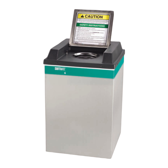
INTRODUCTION The.SUITMATE .unit.is.a.high-speed.swimsuit.water.extractor..It.is.powered.by.a.1/3.horsepower, ® 115-V./.60-Hz.full.grounded.and.fault.protected.electric.motor..The.SUITMATE .unit.weighs.approximately ® 55.pounds.(25kg),.and.measures.15”.x.15”.x.23”. This.manual.contains.Installation.Options,.Safety.Precautions,.Installation.Instructions,.Wiring.Diagram,. Utilities.Location.Diagram,.Maintenance.Instructions,.Troubleshooting.Instructions.detailing.the. removal/replacement.of.mechanical.or.electrical.assemblies,.Micro.Switch.Adjustment.Procedures,.plus.an. exploded.drawing.and.a.Parts.List.. The.SUITMATE .unit.should.only.be.worked.on.by.a.qualified.mechanic/electrician,.or.maintenance.individual. ® All.maintenance.and.troubleshooting.procedures.are.located.in.the.appropriate.sections.of.this.manual. Follow.the.service.procedures.carefully..Always.note.the.location.and.position.of.parts.and.wires.before. removing.them.so.that.reassembly.can.be.done.easily.and.correctly..If.no.specific.reassembly.instructions.are. given,.simply.reverse.the.disassembly.procedure. IMPORTANT INSTALLATION OPTIONS Prior.to.installation.of.the.SUITMATE .unit.determine.how.the.utilities.will.be.connected.. ® 1).Electrical.and.plumbing.connected.internally. 2).Internal.electrical.connection.and.external.plumbing.connection. 3).External.electrical.connection.and.internal.plumbing.connection. 4).External.electrical.and.plumbing.connection. SAFETY When.servicing.the.SUITMATE .unit,.observe.the.following.safety.precautions: ® •.Always.turn.off.the.power.at.the.circuit.breaker.–.place.a.lockout.tag.on.the.circuit.breaker.panel.indicating. ..that.the.breaker.is.not.to.be.turned.on.except.by.authorized.personnel.and.disconnect.the.unit.before.doing. ..any.work.on.the.SUITMATE unit..Simply.turning.off.a.switch.is.NOT.enough. ®. •.Use.only.proper.tools,.test.equipment,.and.work.practices.when.servicing.the.SUITMATE .unit..If.there.are ®... - Page 5 PROPER WALL MOUNTING OF THE SUITMATE UNIT ® The.SUITMATE .unit.should.be.mounted.to.the.wall.with.the.Wall.Mount.Bracket.that.is.provided.with.the.unit... ® The.UTILITIES.LOCATION.DIAGRAM.(page.8).shows.the.recommended.location.for.the.mounting.holes,.the. electrical.service,.and.the.wastewater.outlet.(if.utilized)..The.Wall.Mount.Bracket.must.be.secured.to.a.wall. stud,.or.to.concrete.block.or.cinder.block.wall. WARNING! Anchors in drywall are not sufficient to mount the SUITMATE unit. ® Locating and Securing the Wall Mount Bracket to the Wall The.suggested.height.from.the.floor.to.the.top.of.the.SUITMATE ® unit.is.42.inches.(1050.cm)..At.least.an.additional.10.inches.(250. cm).of.clearance.above.the.SUITMATE .unit.is.needed.for.the ®...
- Page 6 WALL BRACKET MOUNT BRACKET LOWER SUITMATE UNIT ® (front) MOUNTING SCREWS USE APPROPRIATE ANCHORS AND FASTENERS TO MOUNT THE UNIT WALL FOR YOUR SPECIFIC INSTALLATION FLOOR CUTAWAY VIEW OF SUITMATE UNIT ® October 7, 2012 115-V 20-Amp 60-Hz Self-Timed Unit...
- Page 7 To an Approved Sanitary Waste Line This.installation.should.only.be.done.in.accordance.with.all.applicable.local.plumbing.codes.and.regulations... The.unit’s.1-1/4.inch.(31.25.mm).O.D..drain.tailpiece.is.designed.for.connection.with.standard.compression. type.plumbing.fittings..There.is.room.inside.the.housing.for.the.use.of.a.standard.“P”.type.plumbing. connection..The.waste.outlet.should.be.located.in.the.wall.behind.the.unit..The.UTILITIES.LOCATION. DIAGRAM.shows.the.appropriate.location.for.the.waste.duct..Refer.to.UTILITIES.LOCATION.DIAGRAM.on. page.8. PROPER ELECTRICAL CONNECTIONS FOR THE SUITMATE UNIT ® Note: Strictly follow all applicable local electrical codes and regulations. The.SUITMATE .unit.is.equipped.with.a.ground.fault.circuit.interrupter.(GFCI),.that.is.designed.to.be ® connected.to.a.115-V.20-Amp.60-Hz.dedicated.circuit.that.is.protected.by.a.fuse.or.circuit.breaker.of.the. correct.(20.Amp.Maximum).size..A.PLUG-IN.INSTALLATION.IS.NOT.ACCEPTABLE!.The.utilized.circuit.must. be.run.to.the.SUITMATE .unit’s.weatherproof.Junction.Box.that.contains.the.GFCI..A.cable.or.liquid.tight ®...
-
Page 8: Suitmate
SUITMATE WIRING DIAGRAM ® 115-V 20-Amp 60-Hz Self-Timed Unit SUITMATE UNIT CUSTOMER'S ELECTRICAL SERVICE ® 115-V / 20-Amp / 60-HZ GROUND GFCI IS "GROUND FAULT CIRCUIT INTERRUPTER" MOTOR CONTROLLER AND SWITCH GREEN or GREEN/YELLOW AEC2061 (From GFCI To Motor) GREEN... -
Page 9: Testing.and.operation
POSTING THE WALL SIGN Locate.the.top.edge.of.the.sign.60+/-.1/16”.(1524.+/-.2mm).above.the.floor.centered.over.the.SUITMATE .unit... ® At.this.height.the.sign.will.not.be.blocked.when.the.lid.is.raised..It.will.also.serve.as.a.stop.to.keep.the.Lid.from. striking.the.wall.behind.the.unit. The.sign.has.an.adhesive.foam.backing..Be.certain.the.surface.that.the.sign.is.to.be.mounted.to.is.clean.and. dry..Without.touching.the.sign.to.the.wall,.align.the.top.of.the.sign.60+/-.1/16”.(1524.+/-.2mm).above.the.floor. and.at.the.center.of.the.unit..Press.the.sign.to.the.wall.and.rub.firmly.over.the.adhesive.portion.of.the.sign. TESTING AND OPERATION After.the.mounting.and.all.connections.are.complete,.test.the.SUITMATE .unit.as.follows: ® 1).Make.certain.all.packaging.material.is.removed.from.the.unit.including.material.around.the.Motor. 2).Check.to.see.that.the.Basket.is.empty.and.that.the.Lid.moves.freely. 3).Press.down.on.the.Lid..The.unit.will.start.and.run.for.8.seconds..While.the.unit.is.running.it.should.run..smoothly.and.there.should.be.no.excessive.vibration.or.noise. 4).Releasing.the.lid.before.the.unit.automatically.stops.causes.the.Basket.to.stop.within.one.(1).second. 5).Test.the.SUITMATE .unit.by.putting.a.wet.swimsuit.in.the.unit.according.to.the.instructions.on.the.underside ® ..of.the.Lid..If.there.is.excessive.vibration.or.noise.it.is.usually.caused.by.the.improper.loading.of.the..swimsuit..Be.certain.that.the.swimsuit.is.pushed.to.the.bottom.of.the.Basket.and.that.all.material.is.at.least..two.inches.below.the.top.of.the.Basket. INSTALLATION TROUBLESHOOTING If.the.SUITMATE .unit.does.not.operate,.check.the.following: ® 1).Check.to.see.if.there.is.power.to.the.unit..Check.the.circuit.using.an.A.C..voltmeter.set.to.the.appropriate..range;.measure.across.the.“LINE”.side.of.the.GFCI. 2).Make.certain.that.the.GFCI.switch.is.in.the.“ON”.position... 3).Check.the.connections.on.the.GFCI.Junction.Box..Be.certain.there.is.power.on.the.“LOAD”.side.of..the.GFCI. 4).Check.the.SUITMATE .UNIT.TROUBLESHOOTING.section.in.this.manual.for.additional.troubleshooting... - Page 10 115-V 20-Amp 60-Hz Self-Timed Unit This diagram is for reference only! It is not to be used as the sole reference WARNING! for installation of the SUITMATE unit. The installation instructions beginning ® on page 3 must be followed explicitly!
- Page 11 ..step.3.times. c..The.spun.towel.can.then.be.used.to.wipe.down.the.Basket,.the.Black.Plastic.Top,.the.Lid,.and.the..sides.of.the.unit. d..Re-wipe.the.surfaces.(Basket,.Black.Plastic.Top,.Lid,.and.the.exterior.of.the.unit).with.a.fresh.towel..and.clean.water. Never use flammable solvents in or on the SUITMATE unit. ® WARNING! When cleaning around the unit, be careful not to allow water to splash up under the unit as this may damage the motor.
- Page 12 f..If.you.cannot.establish.a.free.flow.of.water.or.the.discharge.water.is.spilling.out.from.under.the.unit,..the.tailpiece.is.plugged.or.the.drain.channels.are.blocked..Locate.the.blockage.by.referring.back.to..step.A.under.Inspection..After.removing.the.blockage,.repeat.steps.C.through.E. g..Reinstall.the.drain.hose.or.P-trap. MONTHLY 1) Case and Top care a..Wipe.down.the.Black.Plastic.Top.with.Armor.All .or.its.equivalent. ® b..Clean.and.polish.the.stainless.steel.Case.with.Liquid.Gold .or.its.equivalent..If.flash.rust.or.stains.are ® ..present,.use.a.Scotch.Brite .pad.or.medium.grade.steel.wool.to.remove.them..Take.care.to.rub ® ..stains.out.by.going.with.the.grain.of.the.case.(up.and.down.–.not.sideways)..Follow.stain.removal.by..polishing.the.Case.with.Liquid.Gold .or.its.equivalent. ® 2) Testing the GFCI a..Locate.the.weatherproof.junction.box.in.the.bottom.rear.of.the.unit..Flip.open.the.cover.of.the..junction.box.to.expose.the.“Test”.and.“Reset”.buttons.on.the.face.of.the.GFCI. b..Test.the.GFCI.by.depressing.the.“Test”.button;.the.“Reset”.button.should.pop.out..Depress.the..“Reset”.button.to.resume.normal.functioning..If.the.“Reset”.button.does.not.pop.out.during.testing..or.is.unable.to.be.depressed.back.into.place,.the.GFCI.may.be.faulty;.please.contact.Extractor..Corporation.at.800-553-3353.for.further.assistance. If.the.unit.does.not.operate,.please.refer.to.the.Troubleshooting.Guide..If.you.have.any.questions.or.problems,. please.contact.Extractor.Corporation.at.800-553-3353. October 7, 2012 115-V 20-Amp 60-Hz Self-Timed Unit...
-
Page 13: Troubleshooting
Problem: The unit is humming when the Lid is depressed, but the Basket is not spinning. Make certain the main electrical power to the unit is turned off – and locked out CAUTION! – before beginning work on the SUITMATE unit. ®... - Page 14 Problem: The GFCI is tripping off every time the unit is run. Make certain the main electrical power to the unit is turned off – and locked out CAUTION! – before beginning work on the SUITMATE unit. ® •.The.SUITMATE .unit.should.be.connected.to.a.115-V,.20-Amp,.60-Hz.dedicated.circuit..If.the.unit...
- Page 15 Problem: The GFCI is tripping off at random times, no specific patter or reason. Make certain the main electrical power to the unit is turned off – and locked out CAUTION! – before beginning work on the SUITMATE unit. ®...
- Page 16 SUITMATE unit. Simply turning off a switch is NOT enough. Use only proper tools, test equip- ® ment, and work practices when servicing the SUITMATE unit. ® If there are questions concerning proper tools, equipment or practices, please call the factory for recommendations at: (Telephone) 800-553-3353, (Fax) 847-742-3552 or (Email) info@suitmate.com.
-
Page 17: Top.and.sub.top.assemblies
CASE ASSEMBLY EC12 BLACK ALUMINUM POP RIVET (6) AEC 1205 Do This FIRST Make.certain.you.have.all.the.correct.parts.and.fasteners.necessary.for.correct.installation..Re-use.any. components.that.are.not.damaged,.otherwise.replace.them..Parts.used.in.this.process:.(6).AEC1205.Black. Aluminum.Pop.Rivets,.(2).AEC1605.Black.Rubber.Brake.Tips,.(3).AEC1240.Aluminum.Pop.Rivets.that.are. required.to.reinstall.the.Sub-Top.. REMOVE TOP ASSEMBLY 1).Remove.the.SUITMATE .unit.from.the.Wall.Mount.Bracket.following.the.instructions.beginning.on.Page.14. ® 2).Place.the.SUITMATE .unit.in.an.upright.position. ® 3).Lift.the.Lid...Remove.the.Black.Rubber.Brake.Tips.from.the.(2).Brake.Rods...If.damaged,.they.must..be.replaced. 4).Remove.the.(6).rivets.from.around.the.outer.edge.of.the.Black.Plastic.Top. a..Punch.out.the.center.of.each.rivet.with.a.small.drift.punch. b..Drill.out.each.rivet. Note: Make certain the drill bit does not reach a depth of more than ½-inch to avoid damaging the Black Plastic Liner. - Page 18 TURNBUCKLE NUT (1) AEC1807 RISER SHUTTLE SUB-TOP ASSEMBLY AEC2020 SUB-TOP GASKET (1) AEC1352 RISER CABLE TURNBUCKLE ALUMINUM POP RIVET (3) AEC1240 October 7, 2012 115-V 20-Amp 60-Hz Self-Timed Unit...
- Page 19 REMOVE SUB-TOP ASSEMBLY 1).Remove.the.Nut.from.the.Turnbuckle.that.is.attached.to.the.Riser.Cable..Set.the.Nut.aside.for.reassembly. 2).Pull.the.Riser.Cable.with.Turnbuckle.down.through.the.hole.in.the.Riser.Shuttle. 3).Remove.the.(2).rivets.from.around.the.outer.edge.of.the.Sub-Top.and.the.(1).rivet.from.the.top. a..Punch.out.the.center.of.each.rivet.with.a.small.drift.punch. b..Drill.out.each.rivet. Note: Make certain the drill bit does not reach a depth of more than ½-inch to avoid damaging the plastic liner. c..Chisel.off.the.rivet.heads...Make.certain.the.rivets.are.completely.removed. 4).Separate.the.Sub-Top.from.the.SUITMATE .unit..Remove.the.Sub-Top.by.grasping.the.sides.and.lifting ® ..straight.up. 5).Remove.rivet.debris.and.any.other.foreign.objects.from.the.liner. REPLACE SUB-TOP ASSEMBLY 1).Place.the.SUITMATE .unit.in.an.upright.position. ®...
-
Page 20: Lid
LID (1) CEC1402 BLACK O-RING (2) AEC1416 LIFT LID LABEL (1) S.S. POP RIVET AEC1234 (4) AEC1410 S.S. NUT (1) AEC1804 S.S. LOCKWASHER (1) AEC1704 HINGE PIN, LEFT (1) BEC1403 S.S. ACTUATOR SCREW (1) AEC1405 LID OPERATING HINGE PIN, RIGHT INSTRUCTIONS (1) (1) BEC1404 AEC1235 - TIMED UNIT... - Page 21 REMOVE LID FROM BLACK PLASTIC TOP Do This FIRST Make.certain.you.have.all.the.correct.parts.and.fasteners.necessary.for.correct.installation..Re-use.any. components.that.are.not.damaged,.otherwise.replace.them..Parts.used.in.this.process:.(2).AEC1410.S.S.. Pop.Rivets,.(2).AEC1416.Black.O-Rings,.(1).AEC1704.S.S..Lock.Washer,.(1).BEC1403.Hinge.Pin,.Left,. (1).AEC1405.Actuator.Screw,.(1).BEC1404.Hinge.Pin,.Right,.and.(1).AEC.1804.S.S..Nut...Plus.any. components.required.to.reinstall.the.Sub.Top.and.Top.Assemblies.(Page.17). REMOVE LID 1).Remove.SUITMATE .unit.from.the.Wall.Mount.Bracket..See.instructions.beginning.on.Page.14. ® 2).Remove.Top.and.Sub-Top.Assemblies..See.instructions.beginning.on.Page.15. 3).Place.the.Top.Assembly.upside.down. 4).Remove.the.Nut.and.Lock.Washer.from.the.Actuator.Screw. 5).Unscrew.the.Actuator.Screw.from.the.Left.Hinge.Pin. 6).Remove.the.(2).rivets.from.the.outer.edge.of.the.S.S..Lid.that.holds.the.Left.Hinge.Pin. a..Punch.out.the.center.of.each.rivet.with.a.small.drift.pin. b..Drill.out.each.rivet. c..Chisel.off.the.rivet.heads..Make.certain.the.rivets.are.completely.removed. 7).Remove.the.hinge.pin.through.the.metal.Lid..Set.the.Left.Hinge.Pin.aside.for.reassembly.later. 8).Remove.the.Lid.from.the.Top.Assembly..Note: A rubber O-ring is located on each hinge between the metal Lid and the plastic Top.
-
Page 22: Riser.cable.assembly
RISER SHUTTLE NUT (1) AEC1314 E-RING (1) AEC1417 RISER SHUTTLE (1) AEC1304 TURNBUCKLE NUT (1) AEC1807 TURNBUCKLE RISER CABLE MICRO SWITCH BOX (1) BEC1207 MICRO SWITCH BOX COVER (1) AEC1245 MACHINE SCREW (2) AEC1831 MICRO SWITCH BOX (1) BEC1207 RISER CABLE SOLD AS EC8 TURNBUCKLE RISER CABLE ASSEMBLY... - Page 23 REMOVE RISER CABLE ASSEMBLY Do this FIRST Make.certain.you.have.all.the.correct.parts.and.fasteners.necessary.for.correct.installation..Re-use.any. components.that.are.not.damaged,.otherwise.replace.them..Parts.used.in.this.process:.(2).AEC1807. Turnbuckle.Nut,.(1).EC8.Riser.Cable.Assembly,.(2).AEC1831.Machine.Screw,.(1).AEC1245.Micro.Switch.Box. Cover..Plus.any.components.required.to.reinstall.the.Sub-Top.and.Top.Assemblies.(Page.17). REMOVE RISER CABLE ASSEMBLY 1).Remove.SUITMATE .unit.from.the.Wall.Mount.Bracket..See.instructions.beginning.on.Page.14. ® 2).Remove.Top.and.Sub-Top.Assemblies..See.instructions.beginning.on.Page.15. 3).Place.the.SUITMATE .unit.in.an.upright.position.with.the.back.of.the.unit.facing.out. ® 4).Remove.the.Micro.Switch.Box.Cover..The.cover.is.held.on.with.(2).Machine.Screws..Remove.the.cover.and..screws.and.set.aside.for.reassembly. 5).Remove.the.Turnbuckle.Nut.from.the.Turnbuckle. 6).Pull.the.Turnbuckle.up.and.out.of.the.hole.in.the.Micro.Switch.arm. 7).Remove.the.Riser.Cable.by.pulling.it.up.through.the.conduit.connector.at.the.top.of.the.unit. REPLACE RISER CABLE ASSEMBLY 1).Reinstall.Sub-Top.Assembly.after.cleaning.out.any.debris.before.starting.with.the.Riser.Cable.replacement. 2).Drop.the.new.Riser.Cable.(with.Turnbuckle).down.through.the.conduit.to.the.Micro.Switch. 3).Insert.the.Turnbuckle.through.the.hole.in.the.Micro.Switch.arm..Replace.the.Nut.(saved.from.step.5.above)..on.the.Turnbuckle. 4).Insert.the.Turnbuckle.on.the.new.Riser.Cable.through.the.hole.in.the.Riser.Shuttle..Replace.the..Turnbuckle.Nut. 5).Replace.Top.Assembly..See.instructions.beginning.on.Page.17. 6).Push.the.Lid.down..The.Micro.Switch.should.NOT.activate.(click).until.the.Lid.is.approximately.¼-inch.from..being.totally.depressed..Adjust.the.alignment.by.tightening.(clockwise.–.will.activate.unit.sooner).or.
-
Page 24: Drive.unit.assembly
DRIVE UNIT ASSEMBLY MOUNTING CONSISTING OF (3) NUTS (AEC1224) AND (3) LOCK WASHERS (AEC1238) BOTTOM VIEW OF SUITMATE UNIT ® FRONT FACE DRIVE UNIT ASSEMBLY (1) EC23 CASE ASSEMBLY (1) EC12 REMOVAL OF DRIVE UNIT NOTE LOCATION OF ALUMINUM SPACER. IT IS REQUIRED TO KEEP THIS SHOCK BUMPER RING IN POSITION. - Page 25 REMOVE DRIVE UNIT ASSEMBLY FROM CASE Do this FIRST Make.certain.you.have.all.the.correct.parts.and.fasteners.necessary.for.correct.installation..Re-use.any. components.that.are.not.damaged,.otherwise.replace.them..Parts.used.in.this.process:.(3).AEC1224.Nuts,. (3).AEC1238.Lock.Washers,.(2).AEC1819.Flange.Fork.Connectors,.(2).AEC1830.Insulated.Connectors,. (1).AEC1813.White.Wire,.(1).AEC1842.Black.Wire,.(1).AEC1841.White.Wire,.and.(1).AEC1813.Green.or.Green/ Yellow.Wire.Plus.any.components.required.to.correctly.reinstall.the.Sub-Top.and.Top.Assemblies.(Page.17). REMOVE DRIVE UNIT ASSEMBLY 1).Remove.SUITMATE .unit.from.the.Wall.Mount.Bracket..See.instructions.beginning.on.Page.14. ® 2).Remove.Top.and.Sub-Top.Assemblies..See.instructions.beginning.on.Page.15. 3).Place.the.SUITMATE .on.its.face.to.expose.the.bottom.of.the.unit. ® 4).Unscrew.the.(2).captive.screws.that.secure.the.Motor.end.cap.from.the.bottom.of.the.Motor. 5).Remove.the.end.cap.with.captive.screws.and.set.it.aside.for.reassembly. 6).Remove.the.Micro.Switch.Box.Cover..The.cover.is.held.on.with.(2).Machine.Screws..Remove.cover.and..screws.and.set.aside.for.reassembly. 7..Disconnect.the.(4).wires.connecting.the.motor.to.the.unit.by.disconnecting.the.wires.from.the.L1.and.L2.terminals..on.the.Motor..Loosen.the.Green.Grounding.screw.and.disconnect.the.green.or.green/yellow.ground.wire. 8).Cut.off.the.(4).wire.connectors.from.the.wires.to.allow.the.wires.to.be.pulled.through.the.90 ..conduit.connector. 9).Pull.the.wires.through.the.90 .conduit.connector.by.pulling.them.from.the.Micro.Switch.Box.about ..2.to.3.inches. 10).Remove.the.90 .conduit.connector.from.the.Motor.by.disconnecting.the.plastic.cable.conduit.from.the ..90 .conduit.connector.and.unscrewing.the.90 .conduit.connector.from.the.Motor.
- Page 26 FOAM STRIP (4) AEC1244 BLACK PLASTIC LINER (1) DEC1213 S.S. HOSE CLAMP (1) AEC1249 BLACK DRAIN HOSE (1) AEC1248 FOAM STRIP (1) AEC1243 CASE (1) DEC1201 October 7, 2012 115-V 20-Amp 60-Hz Self-Timed Unit...
-
Page 27: Liner
REMOVE / REPLACE BLACK PLASTIC LINER FROM CASE Do this FIRST Make.certain.you.have.all.the.correct.parts.and.fasteners.necessary.for.correct.installation..Re-use.any. components.that.are.not.damaged,.otherwise.replace.them..Parts.used.in.this.process:.(4).AEC1244.Foam. Strips,.(1).DEC1213.Black.Plastic.Liner,.(1).AEC1249.S.S..Hose.Clamp,.(1).AEC1248.Black.Drain.Hose,. and.(1).AEC1243.Foam.Strip..Plus.any.components.required.to.properly.reinstall.the.Drive.Unit.Assembly. (Page.23).and.the.Sub-Top.and.Top.Assemblies.(Page.17). REMOVE LINER 1).Remove.SUITMATE .unit.from.the.Wall.Mount.Bracket..See.instructions.beginning.on.Page.14. ® 2).Remove.Top.and.Sub-Top.Assemblies..See.instructions.beginning.on.Page.15. 3).Remove.Drive.Unit.Assembly..See.instructions.beginning.on.Page.23. 4).Place.the.SUITMATE .unit.on.its.face.to.expose.the.bottom.of.the.unit. ® 5).If.the.factory.supplied.drain.hose.was.used,.unscrew.the.hose.clamp.that.holds.the.plastic.drain.tube.to.the..Liner.drain.hose.outlet. 6).Remove.the.drain.hose.and.set.it.aside.for.reassembly. 7).Place.the.SUITMATE .unit.in.an.upright.position. ® 8).From.the.top.of.the.SUITMATE unit,.grasp.the.lip.of.the.Black.Plastic.Liner.and.pull.straight.up..Be.careful ®..not.to.damage.the.Liner..If.the.Liner.is.damaged,.it.must.be.replaced. REPLACE LINER 1).Place.the.Liner.into.the.case.using.care.not.to.damage.it. 2).If.the.factory.supplied.drain.hose.was.used,.reinstall.it.using.the.hose.clamp.removed.in.step.5.above. - Page 28 BASKET, HUB, AND DISC ASSEMBLY (1) EC22 HUB ROLL PIN (1) AEC1506 S.S. THREADED BRAKE ROD (2) AEC1620 SHORT COMPRESSION SPRING (2) AEC1622 MOUNTING PLATE WITH BRAKE LEVER ARMS (1) EC18 MOTOR (1) BEC1502 S.S. LOCKNUT (2) AEC1624 October 7, 2012 115-V 20-Amp 60-Hz Self-Timed Unit...
-
Page 29: Brake.rods,.Basket,.Hub,.And.brake.disc.assembly
Basket and Brake Disc Assembly from the Motor shaft. Be careful not to damage the Hub or the Motor Mounting Plate. If the Hub is “frozen” to the Motor shaft, please contact Extractor Corporation at: (Telephone) 800-553-3353, (Fax) 847-742-3552, or (E-Mail) info@suitmate.com and explain your problem. REPLACE BRAKE RODS, BASKET, HUB, AND BRAKE DISC ASSEMBLY 1).Push.the.Basket,.Hub,.and.Brake.Disc.Assembly.onto.the.Motor.Shaft.so.that.the.hole.in.the.Hub.lines.up. - Page 30 BASKET (1) BEC1708 BASKET AND HUB ASSEMBLY IS EC20 HUB (1) CEC1701 S.S. BRAKE DISC (1) BEC1702 S.S. LOCKWASHER (3) AEC1704 S.S. SCREW (3) AEC1703 October 7, 2012 115-V 20-Amp 60-Hz Self-Timed Unit...
-
Page 31: Brake.disc.and.basket
REMOVE / REPLACE BRAKE DISC AND BASKET Do this FIRST Make.certain.you.have.the.correct.parts.and.fasteners.necessary.for.correct.installation..Re-use.any. components.that.are.not.damaged,.otherwise.replace.them..Parts.used.in.this.process:.(1).EC20.Basket.and. Hub.Assembly,.(1).BEC1702.S.S..Brake.Disc,.(3).AEC1704.S.S..Lockwashers,.(3).AEC1703.S.S..Screws.. Plus.any.components.required.to.properly.reinstall.the.Drive.Unit.Assembly.(Page.23).and.the.Sub-Top.and. Top.Assemblies.(Page.17). REMOVE BRAKE DISC AND BASKET 1).Remove.SUITMATE .unit.from.the.Wall.Mount.Bracket..See.instructions.beginning.on.Page.14. ® 2).Remove.Top.and.Sub-Top.Assemblies..See.instructions.beginning.on.Page.15. 3).Remove.Drive.Unit.Assembly..See.instructions.beginning.on.Page.23. 4).Remove.Brake.Rods,.Basket,.Hub.and.Brake.Disc.Assembly..See.instructions.beginning.on.Page.27. 5).Remove.the.(3).screws.and.washers.from.the.bottom.of.the.Hub.Assembly..Set.them.aside.for.reassembly. 6).Remove.the.Brake.Disc.from.the.Hub..The.Brake.Disc.may.have.to.be.tapped.off.using.a.small.plastic..hammer..Replace.if.necessary. REPLACE BRAKE DISC AND BASKET 1).Replace.the.Brake.Disc.by.assembling.it.over.the.Hub.and.aligning.the.(3).holes..Secure.the.Brake.Disc..using.(3).screws.and.(3).Lock.Washers. 2).Reinstall.the.Brake.Disc.and.Basket.Assembly.onto.the.motor.shaft..See.instructions.beginning.on.Page.27. 3).Reinstall.the.Brake.Rods.to.the.Drive.Unit.Assembly.by.installing.the.locknut.and.spring.on.each.Brake.Rod. 4).Reinstall.Drive.Unit.Assembly..See.instructions.beginning.on.Page.23. 5).Reinstall.Sub-Top.and.Top.Assemblies..See.instructions.beginning.on.Page.17. -
Page 32: Brake.lever
BRAKE LEVER ASSEMBLY (2) EC16 S.S. COMPRESSION SPRING (2) AEC1612 FLAT WASHER (2) AEC1609 WHITE PLASTIC BUSHING (2) AEC1603 MOTOR MOUNTING PLATE ASSEMBLY (1) EC17 BRAKE LEVER ASSEMBLY (1) EC16 NYLON WASHER BRAKE SUPPORT (2) AEC1827 BRACKET (1) AEC1601 WHITE PLASTIC BUSHING S.S. - Page 33 Make.certain.you.have.all.the.correct.parts.and.fasteners.necessary.for.correct.installation..Re-use.any. components.that.are.not.damaged,.otherwise.replace.them..Extractor.recommends.that.a.Brake.Parts.Kit. AEC2300.be.purchased..Parts.used.in.this.process:.(2).AEC1614.Brake.Hinge.Pins,.(4).AEC1603.White. Plastic.Bushings,.(4).AEC1927.Nylon.Washers,.(2).EC16.Brake.Lever.Assemblies,.(2).AEC1601.Brake. Support.Brackets,.(2).AEC1823.S.S..Pop.Rivets..Plus.any.components.required.to.properly.reinstall.the.Basket. and.Brake.Disc.Assembly.(Page.29),.the.Brake.Pad.Supports.(Page.33),.the.Drive.Unit.Assembly.(Page.23),. and.the.Sub-Top.and.Top.Assemblies.(Page.17). REMOVE BRAKE LEVER 1).Remove.SUITMATE .unit.from.the.Wall.Mount.Bracket..See.instructions.beginning.on.Page.14. ® 2).Remove.Top.and.Sub-Top.Assemblies..See.instructions.beginning.on.Page.15. 3).Remove.Drive.Unit.Assembly..See.instructions.beginning.on.Page.23. 4).Remove.Basket,.Hub,.and.Brake.Disc.Assembly..See.instructions.beginning.on.Page.27. Note: Make certain that the C-clamps have been removed from the Brake Levers. 5).Remove.the.Brake.compression.spring,.washer,.and.plastic.bushing..Set.them.aside.for.reassembly. Note: Pay attention to the location of the spring, washer and plastic bushing. It is recommended that the compression spring be replaced with a new compression spring.
-
Page 34: Brake.pad
1/2 x 3/16 S.S. POP RIVET (2) AEC1208 BRAKE PAD - AEC1608 MAKE CERTAIN THAT COUNTERSUNK HOLES ARE UP! BRAKE PAD SUPPORT (2) AEC1607 BRAKE PAD EC16 ASSEMBLY EC14 BRAKE LEVER ARM AEC1602 1/8 x 3/16 S.S. POP RIVET (2) AEC1208 EC16 BRAKE LEVER ASSEMBLY - 2 REQUIRED October 7, 2012 115-V 20-Amp 60-Hz Self-Timed Unit... - Page 35 REMOVE AND REPLACE BRAKE PADS Do this FIRST Make.certain.you.have.all.the.correct.parts.and.fasteners.necessary.for.correct.installation..Re-use.any.parts. that.are.not.damaged,.otherwise.replace.them..Extractor.recommends.that.a.Brake.Parts.Kit.AEC2300.be. purchased..Parts.used.in.this.process:.(2).AEC1607.Brake.Pad.Supports,.(2).AEC1608.Brake.Pads,.(8). AEC1208.S.S..Pop.Rivets..Plus.any.components.required.to.properly.reinstall.the.Basket,.Hub.and.Brake.Disc. Assembly.(Page.27),.the.Brake.Lever.Assemblies.(Page.31),.the.Drive.Unit.Assembly.(Page.23),.and.the. Sub-Top.and.Top.Assemblies.(Page.17). REMOVE BRAKE PADS 1).Remove.SUITMATE .unit.from.the.Wall.Mount.Bracket..See.instructions.beginning.on.Page.14. ® 2).Remove.Top.and.Sub-Top.Assemblies..See.instructions.beginning.on.Page.15. 3).Remove.Drive.Unit.Assembly..See.instructions.beginning.on.Page.23. 4).Remove.Basket,.Hub,.and.Brake.Disc.Assembly..See.instructions.beginning.on.Page.27. 5).Remove.Brake.Lever.Assembly..See.instructions.beginning.on.Page.31. 6).Remove.the.rivets.that.hold.the.Brake.Pad.support.to.the.Brake.Lever.Assembly. a..Punch.out.the.center.of.each.rivet.with.a.small.drift.punch. b..Drill.out.the.rivet. c..Chisel.off.the.rivet.head..Make.certain.the.rivet.is.completely.removed. 7).Remove.the.Brake.Pad.Assembly. 8).Remove.the.rivets.that.hold.the.Brake.Pad.to.the.Brake.Pad.support.bracket. a..Punch.out.the.center.of.each.rivet.with.a.small.drift.punch. b..Drill.out.the.rivet. c..Chisel.off.the.rivet.head..Make.certain.the.rivet.is.completely.removed. 9).Remove.the.old.Brake.Pad. REPLACE BRAKE PAD 1).Align.the.holes.on.the.new.Brake.Pad.with.the.holes.of.the.Brake.Pad.support. Note: Make certain the Brake Pad has the Countersunk holes on the top.
- Page 36 THROUGH AEC1228 NOTE: THE SIDE OF THE SHOCK BUMPER RING MUST BE ALIGNED AGAINST THE END OF THE ALUMINUM SPACER (AEC1822) SHOCK BUMPER RING AEC1223 HEX NUT AEC1224 REAR OF SUITMATE UNIT ® SHOCK MOUNT AEC1202 POSITION OF ELECTRICAL CONNECTOR...
-
Page 37: Shock.mounts
REMOVE AND REPLACE SHOCK MOUNTS Do this FIRST Make.certain.you.have.all.the.correct.parts.and.fasteners.necessary.for.correct.installation..Re-use.any. components.that.are.not.damaged,.otherwise.replace.them..Parts.used.in.this.process:.(3).AEC1202.Shock. Mounts,.(3).AEC1224.S.S..Nuts..Plus.any.components.required.to.properly.reinstall.the.Drive.Unit.Assembly. (Page.23).and.the.Sub-Top.and.Top.Assemblies.(Page.17). REMOVE SHOCK MOUNTS 1).Remove.SUITMATE .unit.from.the.Wall.Mount.Bracket..See.instructions.beginning.on.Page.14. ® 2).Remove.Top.and.Sub-Top.Assemblies..See.instructions.beginning.on.Page.15. 3).Remove.Drive.Unit.Assembly..See.instructions.beginning.on.Page.23. 4).Remove.the.S.S..Nut.that.secures.the.Shock.Mount.to.the.Shock.Bumper.Ring. 5).Remove.the.Shock.Mount.from.the.Shock.Bumper.Ring. REPLACE SHOCK MOUNTS 1).Install.the.new.Shock.Mount.to.the.Shock.Bumper.Ring.and.secure.using.the.S.S..Nut. Note: Use new S.S. Nuts if necessary. 2).Reinstall.Drive.Unit.Assembly..See.instructions.beginning.on.Page.23. 3).Reinstall.Sub-Top.and.Top.Assemblies..See.instructions.beginning.on.Page.17. 4).Reinstall.SUITMATE .unit.to.the.Wall.Mount.Bracket..See.instructions.beginning.on.Page.14. ® 5).Retest.the.SUITMATE .unit.for.proper.operation,.refer.to.TESTING.AND.OPERATION.on.Page.7. - Page 38 THROUGH AEC1228 NOTE: THE SIDE OF THE SHOCK BUMPER RING MUST BE ALIGNED AGAINST THE END OF THE ALUMINUM SPACER (AEC1822) SHOCK BUMPER RING AEC1223 HEX NUT AEC1224 REAR OF SUITMATE UNIT ® SHOCK MOUNT AEC1202 POSITION OF ELECTRICAL CONNECTOR...
-
Page 39: Shock.bumper.rings
Note: Be certain to use the small washer (AEC1228) in riveting the Shock Bumper Ring to the Motor Mounting Plate. Make certain the Shock Bumper Ring Assembly is properly aligned with the other two Bumper Rings. Failure to do so will prevent proper reassembly of the SUITMATE unit. - Page 40 DRIVE UNIT ASSEMBLY MOUNTING CONSISTING OF (3) NUTS (AEC1224) AND (3) LOCK WASHERS (AEC1238) BOTTOM VIEW OF SUITMATE UNIT ® FRONT FACE DRIVE UNIT ASSEMBLY (1) EC23 CASE ASSEMBLY (1) EC12 REMOVAL OF DRIVE UNIT BACK OF UNIT NOTE LOCATION OF ALUMINUM SPACER.
- Page 41 HEX HEAD BOLT (4) AEC1505 LOCKWASHER (4) AEC1203 MOUNTING PLATE/BRAKE LEVERS ASSEMBLY EC18 MOTOR MOUNT SPACER (3) AEC1504 MOTOR (1) BEC1502 ALUMINUM SPACER (1) AEC1822: NOTE LOCATION OF THIS SPACER AS REINSTALLATION AT PROPER LOCATION IS A REQUIREMENT. THE SIDE OF THE SHOCK BUMPER MUST BE ALIGNED AGAINST THE END OF THE ALUMINUM SPACER.
- Page 42 Green or Green/Yellow Ground Wire with Flange Fork Connector secured to the Green Ground Screw and Black Wire with Female (Flag) Ground Terminal of the Motor. Connector secured to the post of Terminal L1. White Wire with Flange Fork Connector secured to the screw in Terminal L2.
- Page 43 REMOVE AND REPLACE MOTOR Do this FIRST Make.certain.you.have.all.the.correct.parts.and.fasteners.necessary.for.correct.installation..Re-use.any.parts. that.are.not.damaged,.otherwise.replace.them..Parts.used.in.this.process:.(1).AEC1822.Aluminum.Spacer,. (3).AEC1504.Motor.Mount.Spacers,.(4).AEC1505.Hex.Head.Bolts,.(4).AEC1203.Lock.Washers,.and.(1). BEC1502.Motor.115-V.60-Hz..Plus.any.components.required.to.properly.reinstall.the.Basket,.Hub,.and.Brake. Disc.Assembly.(Page.27),.the.Drive.Unit.Assembly.(Page.23),.and.the.Sub-Top.and.Top.Assemblies.(Page.17). REMOVE MOTOR FROM MOUNTING PLATE 1).Remove.SUITMATE .unit.from.the.Wall.Mount.Bracket..See.instructions.beginning.on.Page.14. ® 2).Remove.Top.and.Sub-Top.Assemblies..See.instructions.beginning.on.Page.15. 3).Remove.Drive.Unit.Assembly..See.instructions.beginning.on.Page.23. 4).Remove.Basket,.Hub,.and.Brake.Disc.Assembly..See.instructions.beginning.on.Page.27. 5).Referring.to.photograph.and.drawings.on.Pages.38.through.40,.remove.the.(4).Hex.Head.Bolts,.Lock..Washers,.and.Motor.Mount.Spacers.that.hold.the.Motor.to.the.Mounting.Plate... Note: Examine the placement of the (4) spacers, especially the AEC1822 Aluminum Spacer next to the Shock Bumper Ring.
-
Page 44: Gfci
GFCI MOUNTING SCREWS (2) AEC1820 BACK OF UNIT GFCI BOTTOM VIEW OF SUITMATE UNIT ® October 7, 2012 115-V 20-Amp 60-Hz Self-Timed Unit... - Page 45 ELECTRICAL ASSEMBLIES 115-V 20-Amp 60-Hz Self-Timed Unit GENERAL When.servicing.the.SUITMATE .unit,.observe.the.following.safety.precautions: ® Always.turn.off.the.power.at.the.circuit.breaker.–.place.a.lockout.tag.on.the.circuit.breaker.panel.indicating.that. the.breaker.is.not.to.be.turned.on.except.by.authorized.personnel.–.and.disconnect.the.unit.before.doing.any. work.on.the.SUITMATE .unit..Simply.turning.off.a.switch.is.NOT.enough. ® Use.only.proper.tools,.test.equipment,.and.work.practices.when.servicing.the.SUITMATE .unit..If.there.are.any. ® questions.concerning.proper.tools,.equipment.or.practices,.please.contact.the.factory.for.recommendations.at:. (Telephone).(800).553-3353,.(Fax).847-742-3552,.or.(E-Mail).info@suitmate.com. Due.to.critical.tolerances,.use.only.specified.replacement.parts..See.the.SUITMATE .UNIT.PARTS.AND ® ASSEMBLIES.list.in.this.manual. REMOVE AND REPLACE GFCI The.GFCI.can.be.serviced.from.the.bottom.of.the.unit.without.removing.the.unit.from.the.wall. Do this FIRST Make.certain.you.have.all.the.correct.parts.and.fasteners.necessary.for.correct.installation..Parts.used.in.this. process:.(1).AEC2009.GFCI.115V.60Hz. REMOVE GFCI 1).Turn.off.the.main.electrical.power.to.the.unit.–.place.a.lockout.tag.on.the.circuit.breaker.panel.indicating.that..the.breaker.is.not.to.be.turned.on.except.by.authorized.personnel,.and.disconnect.the.unit.before.doing.any..work.on.the.SUITMATE .unit..Simply.turning.off.a.switch.in.NOT.enough.
-
Page 46: Micro.switch
RISER SHUTTLE AEC1304 TURNBUCKLE NUT (2) AEC1807 SOLD AS EC8 TURNBUCKLE RISER CABLE MICRO SWITCH BOX NYLON STUD SPACER (2) AEC1809 MICRO SWITCH SCREWS (2) AEC1828 HOT WIRE (BLACK) MICRO SWITCH AEC1843 BOX (1) BEC1207 HOT WIRE (BLACK) AEC1815 S.S. NUT (2) AEC1804 S.S. - Page 47 REMOVE AND REPLACE MICRO SWITCH Do this FIRST Make.certain.you.have.all.the.correct.parts.and.fasteners.necessary.for.correct.installation..Parts.used.in.this. process:.(1).AEC1810.Micro.Switch,.(2).AEC1808.Star.Lock.Washers,.(2).AEC1804.S.S..Nuts,.(2).AEC1831. Machine.Screws,.(1).AEC1250.Gasket,.and.(1).AEC1245.Micro.Switch.Box.Cover. REMOVE MICRO SWITCH 1).Turn.off.the.main.electrical.power.to.the.unit.–.place.a.lockout.tag.on.the.circuit.breaker.panel.indicating.that..the.breaker.is.not.to.be.turned.on.except.by.authorized.personnel.and.disconnect.the.unit.before.doing.any..work.on.the.SUITMATE .unit..Simply.turning.off.a.switch.is.NOT.enough. ® 2).Remove.SUITMATE .unit.from.the.Wall.Mount.Bracket..See.instructions.beginning.on.Page.14..Place.the ® ..SUITMATE .unit.on.its.front.side. ® 3).Remove.the.Micro.Switch.Box.Cover.to.expose.the.Micro.Switch.and.Riser.Cable.. 4).Unscrew.the.Turnbuckle.Nut.on.the.Riser.Cable.Turnbuckle.to.free.the.Micro.Switch’s.arm..Set.the.nut..aside.for.reassembly. 5).Remove.the.Nuts.and.Lock.Washers.to.access.the.Micro.Switch..Set.the.hardware.aside.for.reassembly.. 6).Remove.the.Micro.Switch.from.the.mounting.studs. REPLACE MICRO SWITCH 1).Remove.the.wires,.one.at.a.time,.and.put.each.wire.in.the.matching.position.on.the.new.Micro.Switch. 2).Place.the.newly.wired.Micro.Switch.on.the.mounting.studs..Make.certain.the.switch.arm.extends.to.the..right..Use.the.Nuts.and.Lock.Washers.previously.removed.to.secure.the.new.Micro.Switch... Note: Do not over tighten the Nuts! 3).Put.the.threaded.end.of.the.Riser.Cable.Turnbuckle.through.the.hole.in.the.arm.of.the.Micro.Switch..Use.
- Page 48 RISER SHUTTLE AEC1304 TURNBUCKLE NUT (2) AEC1807 SOLD AS EC8 TURNBUCKLE RISER CABLE MICRO SWITCH BOX NYLON STUD SPACER (2) AEC1809 MICRO SWITCH SCREWS (2) AEC1828 HOT WIRE (BLACK) MICRO SWITCH AEC1843 BOX (1) BEC1207 HOT WIRE (BLACK) AEC1815 S.S. NUT (2) AEC1804 S.S.
- Page 49 REMOVE AND REPLACE TIMER Do this FIRST Make.certain.you.have.all.the.necessary.parts.and.fasteners.necessary.for.correct.installation..Parts.used.in. this.process:.(1).AEC1219.Timer,.(4).AEC1809.Nylon.Spacers,.(2).AEC1808.Star.Lock.Washers,.(2).AEC1804. S.S..Nuts,.(2).AEC1831.Machine.Screws,.(1).AEC1250.Gasket,.and.(1).AEC1245.Micro.Switch.Box.Cover. REMOVE TIMER 1).Turn.off.the.main.electrical.power.to.the.unit.–.place.a.lockout.tag.on.the.circuit.breaker.panel.indicating.that..the.breaker.is.not.to.be.turned.on.except.by.authorized.personnel.and.disconnect.the.unit.before.doing.any..work.on.the.SUITMATE .unit..Simply.turning.off.a.switch.is.NOT.enough. ® 2).Remove.SUITMATE .unit.from.the.Wall.Mount.Bracket..See.instructions.beginning.on.Page.14..Place.the ® ..SUITMATE .on.its.front.side. ® 3).Remove.the.Micro.Switch.Box.Cover.to.expose.the.Micro.Switch.and.Riser.Cable.lower.assembly.by..unscrewing.(2).screws..Place.the.screws.aside.for.reassembly.later. 4).Remove.the.(2).Nuts,.(2).Lock.Washers.and.(4).Spacers.to.access.the.Timer..Set.the.hardware.aside.for..reassembly. 5).Remove.the.Timer.from.the.mounting.studs. REPLACE TIMER 1).Remove.the.wires,.one.at.a.time,.and.put.each.wire.in.the.matching.position.on.the.new.Timer. 2).Place.the.newly.wired.Timer.on.the.mounting.studs..Use.the.(4).Spacers.(2).Nuts,.and.(2).Lock.Washers..previously.removed.to.secure.the.new.Timer... Note: Do not over tighten the Nuts! 3).Replace.the.Micro.Switch.Box.Cover.and.secure.it.in.place.using.the.previously.removed.screws.
- Page 50 RISER SHUTTLE NUT (1) AEC1314 E-RING (1) AEC1417 RISER SHUTTLE (1) AEC1304 TURNBUCKLE NUT (1) AEC1807 TURNBUCKLE RISER CABLE MICRO SWITCH BOX (1) BEC1207 MICRO SWITCH BOX COVER (1) AEC1245 MACHINE SCREW (2) AEC1831 MICRO SWITCH BOX (1) BEC1207 RISER CABLE SOLD AS EC8 TURNBUCKLE RISER CABLE ASSEMBLY...
- Page 51 ..Riser.Cable.Assembly.by.unscrewing.the.(2).Machine.Screws..Place.the.screws.aside.for.reassembly.later. NOTE: Older units may have rivets instead of screws. Make certain the main electrical power to the unit is turned off – and locked out CAUTION! – before beginning work on the SUITMATE unit. ® CHECKING MICRO SWITCH ALIGNMENT 1).Stand.the.unit.upright.and.reaching.from.the.rear.push.the.Lid.down.on.the.top.of.the.unit.to.determine.if.the.
- Page 52 EXPLODED VIEW October 7, 2012 115-V 20-Amp 60-Hz Self-Timed Unit...
- Page 53 Brake Pad Drive Unit Mounting Plate with Brake Lever Assembly Assembly Assembly Arms Assembly EC17 Motor Mounting Plate Assembly EC22 EC20 Basket Basket, Hub, Assembly & Disc Brake Assembly SUITMATE ® Unit Assembly October 7, 2012 115-V 20-Amp 60-Hz Self-Timed Unit...
- Page 54 SUITMATE UNIT PARTS AND ASSEMBLY LIST ® 115-V 20-Amp 60-Hz Self-Timed Unit October 7, 2012 115-V 20-Amp 60-Hz Self-Timed Unit...
- Page 55 SUITMATE UNIT PARTS AND ASSEMBLY LIST ® 115-V 20-Amp 60-Hz Self-Timed Unit October 7, 2012 115-V 20-Amp 60-Hz Self-Timed Unit...
- Page 56 SUITMATE UNIT PARTS AND ASSEMBLY LIST ® 115-V 20-Amp 60-Hz Self-Timed Unit October 7, 2012 115-V 20-Amp 60-Hz Self-Timed Unit...
- Page 57 SUITMATE UNIT PARTS AND ASSEMBLY LIST ® 115-V 20-Amp 60-Hz Self-Timed Unit NOTE: Please contact Extractor Corporation at 800-553-3353 if there are any questions in regards to SUITMATE® parts and components. October 7, 2012 115-V 20-Amp 60-Hz Self-Timed Unit...
- Page 58 MAINTENANCE SIGN OFF LOG Weekly Physical Inspection Date Performed By: Date Performed By: Date Performed By: Date Performed By: Date Performed By: Hygenic Cleaning Date Performed By: Date Performed By: Date Performed By: Date Performed By: Date Performed By: Flushing Date Performed By: Date...
Need help?
Do you have a question about the 115V/60Hz and is the answer not in the manual?
Questions and answers
basket is lop sided
To fix a lopsided basket on a Suitmate 115V/60Hz unit, follow these steps:
1. Check Basket Alignment: Ensure the basket is properly seated and rotates freely without obstruction.
2. Inspect Hub and Roll Pin: Rotate the hub to check if the roll pin holding the basket, hub, and brake disc assembly to the motor shaft is intact.
3. Remove and Reinstall Basket Assembly:
- Use a hammer and a 3/16” drift punch to remove the hub roll pin.
- Carefully pry up the hub using a small pry bar or large screwdriver to free it from the motor shaft.
- Rotate the basket, hub, and brake disc assembly while applying even pressure.
- Remove and reinstall the basket, ensuring proper alignment.
4. Replace Hub Roll Pin: Use a new hub roll pin (Part Number AEC1506) during reassembly.
5. Reassemble and Test: Ensure all components are securely reinstalled and test the unit for proper operation.
If the hub is stuck to the motor shaft, contact Extractor Corporation for assistance.
This answer is automatically generated