Table of Contents

Related Manuals for Mercury R3-30


Summary of Contents for Mercury R3-30
- Page 1 Operation Maintenance Installation Warranty Manual...
- Page 3 EU Compliance Statement Attwood Corporation hereby declares that the MotorGuide R3 trolling motor is in compliance with the essential requirements and other relevant provisions of the 99/5/EC R&TTE directive. CE Declaration Manufacturer: Attwood Corporation Address: 1016 N. Monroe Lowell, MI 49415 USA Telephone: 616‑897‑9241 Authorized Representative: Brunswick Marine Parc Industriel de Petit‑Rechain...
- Page 4 MotorGuide, Lowell, Michigan U.S.A. Copyright and Trademark Information © MERCURY MARINE. All rights reserved. Reproduction in whole or in part without permission is prohibited. Alpha, Axius, Bravo One, Bravo Two, Bravo Three, Circle M with Waves Logo, K‑planes, Mariner, MerCathode, MerCruiser, Mercury, Mercury with Waves Logo, Mercury Marine, Mercury Precision Parts, Mercury Propellers, Mercury Racing, MotorGuide, OptiMax, Quicksilver, SeaCore, Skyhook, SmartCraft, Sport‑Jet,...
-
Page 5: Table Of Contents
Warranty Information MotorGuide Limited Two Year Warranty..............1 General Information Boater's Responsibilities....................3 Protecting People in the Water..................3 Passenger Safety Message..................3 Safe Boating Suggestions.................... 3 Product Overview R3‑30/R3‑40/R3‑45/R3‑55 MotorGuide Trolling Motor..........5 Specifications....................... 6 Wiring and Battery Information Wiring and Battery Information.................. - Page 6 Maintenance Trolling Motor Care....................17 Inspection and Maintenance Schedule..............17 Lubricating the Pivot Points..................18 Battery Inspection...................... 18 Propeller Replacement....................18 MotorGuide Accessories Inquiries................19 Troubleshooting Trolling Motor Performance..................20 Owner Service Assistance Mercury Marine Service Offices................. 22...
-
Page 7: Warranty Information
MotorGuide products due to repairs performed by anyone other than the MotorGuide Factory Service Center. Neither MotorGuide nor Mercury Marine is responsible for failure or damage caused by improper installation, set‑up, preparation, or previous service or repair errors. - Page 8 3) use of an accessory or part not manufactured by MotorGuide/Mercury; 4) alteration or removal of parts; 5) opening the lower unit (motor) by anyone other than the Factory Service Center will void this warranty.
-
Page 9: General Information
GENERAL INFORMATION Boater's Responsibilities The operator (driver) is responsible for the correct and safe operation of the boat and safety of its occupants and general public. It is strongly recommended that each operator (driver) read and understand this entire manual before operating the trolling motor. - Page 10 GENERAL INFORMATION Use flotation devices. It is the law to have an approved personal flotation device of suitable size for each person aboard and have it readily accessible. Do not overload your boat. Most boats are rated and certified for maximum load (weight) capacities, refer to your boat capacity plate.
-
Page 11: Product Overview
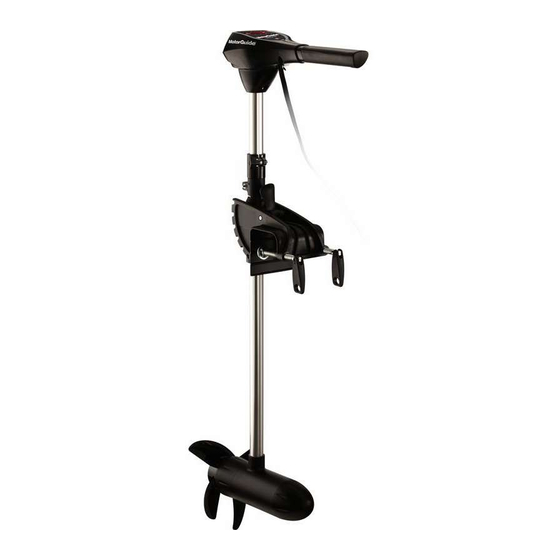
PRODUCT OVERVIEW R3‑30/R3‑40/R3‑45/R3‑55 MotorGuide Trolling Motor 56547 Top housing Extendable speed control tiller handle Serial number Positive and negative battery leads Depth adjustment collar (R3‑45/55 model shown) Tilt lock release lever (R3‑45/55 model shown) Transom clamp screws Column Lower unit Propeller Clamp bracket (R3‑45/55 model shown) Steering tension collar... -
Page 12: Specifications
PRODUCT OVERVIEW Specifications Speeds Freshwater/ Peak Shaft Model Control Volts Forward/ Saltwater Thrust Length Reverse Extendable 13.6 kgf 76.2 cm R3‑30 hand/ Freshwater 12 V (30 lbf) (30 in.) twist‑tiller Extendable 18.1 kgf 91.4 cm R3‑40 hand/ Freshwater 12 V (40 lbf) (36 in.) twist‑tiller... -
Page 13: Wiring And Battery Information
WIRING AND BATTERY INFORMATION Wiring and Battery Information WARNING An operating or charging battery produces gas that can ignite and explode, spraying out sulfuric acid, which can cause severe burns. Ventilate the area around the battery and wear protective equipment when handling or servicing batteries. WARNING Performing service or maintenance without first disconnecting the battery can cause product damage, personal injury, or death due to fire, explosion, electrical... -
Page 14: Wire And Cable Routing
WIRING AND BATTERY INFORMATION When charging batteries, an explosive gas mixture forms in each cell. Part of this gas escapes through holes in the vent plugs and may form an explosive atmosphere around the battery if ventilation is poor. This explosive gas may remain in or around the battery for several hours after it has been charged. - Page 15 WIRING AND BATTERY INFORMATION 3. Connect a common ground bond from the trolling motor battery negative (–) terminal to the engine starting battery negative (–) terminal. Power cables to trolling motor Manual reset circuit breaker Trolling motor battery Engine starting battery Power cables to engine Common ground bond 45086...
-
Page 16: Trolling Motor Installation And Operation
TROLLING MOTOR INSTALLATION AND OPERATION Transom Mount Installation NOTE: The R3‑30 and R3‑40 fit transoms up to 7.62 cm (3 in.). The R3‑45 and R3‑55 fit transoms up to 8.9 cm (3.5 in.). 1. Place the trolling motor on the transom of the boat. IMPORTANT: Overtightening the transom clamp screws can weaken or damage the mount bracket. - Page 17 TROLLING MOTOR INSTALLATION AND OPERATION • R3‑30 and R3‑40 models ‑ push down on the tilt lock release pin while simultaneously pulling on the trolling motor head/column. Do not exert downward force on the tiller handle to assist in tilting the trolling motor. •...
- Page 18 TROLLING MOTOR INSTALLATION AND OPERATION 2. When the desired tilt position is achieved, release the tilt lock release pin/lever. Verify that the latch pin is securely engaged. 56581 Tilt lock release lever (R3‑45 and R3‑55 model shown) Latch pin Tilt lock release pin (R3‑30 and R3‑40 model shown) DEPLOYING THE MOTOR CAUTION Moving parts, such as hinges and pivot points, can cause serious injury.
-
Page 19: Adjusting The Steering Tension
TROLLING MOTOR INSTALLATION AND OPERATION 1. Firmly grasp the trolling motor head/column and press on the tilt lock release pin/lever. 56581 Tilt lock release lever (R3‑45 and R3‑55 model shown) Latch pin Tilt lock release pin (R3‑30 and R3‑40 model shown) 2. -
Page 20: Adjusting The Motor Depth
TROLLING MOTOR INSTALLATION AND OPERATION 2. Turn the steering tension knob counterclockwise to decrease steering effort. 56607 Steering tension knob (R3‑45 and R3‑55 model shown) Friction strip Steering tension knob (R3‑30 and R3‑40 model shown) Adjusting the Motor Depth Adjusting the depth of the motor improves trolling motor performance in various water depths. -
Page 21: Speed Control-Hand-Operated Models
TROLLING MOTOR INSTALLATION AND OPERATION Firmly grasp the column with one hand while turning the depth collar adjustment knob counterclockwise until the motor column slides freely. To secure the column in the desired depth position, turn the depth collar adjustment knob clockwise and tighten securely. -
Page 22: Battery Indicator Light (Digital Models Only)
TROLLING MOTOR INSTALLATION AND OPERATION Digital variable speed models allow you to select any speed from 0–10 in forward or reverse. 45750 Forward speed control Reverse speed control Battery Indicator Light (Digital Models Only) The battery indicator light (located on the head cover) provides battery state‑of‑charge information at a glance. -
Page 23: Trolling Motor Care
MAINTENANCE Trolling Motor Care To keep your trolling motor in the best operating condition and retain its dependability, it is important that your trolling motor receive periodic inspections and maintenance. We urge you to keep it maintained properly to ensure the safety of you and your passengers. -
Page 24: Lubricating The Pivot Points
MAINTENANCE IMPORTANT: Trolling motors stored in temperatures below 0 °C (32 °F) should be operated slowly for a minimum of 15 minutes before going above 30% operation. Lubricating the Pivot Points To reduce friction, lubricate the following pivot points periodically: •... -
Page 25: Motorguide Accessories Inquiries
MAINTENANCE IMPORTANT: Remove the propeller nut with a prop wrench. Using another tool may damage the propeller nut or shaft. If the propeller cannot be removed easily, use a rubber mallet to lightly tap the back side of the opposite blade. If the propeller cannot be removed, have the propeller removed by an authorized dealer. -
Page 26: Troubleshooting
TROUBLESHOOTING Trolling Motor Performance Symptom Possible Cause Resolution Weak battery Refer to Wiring and Battery Loose or corroded battery Information. connections Propeller is loose, Refer to Maintenance. damaged, or off‑balance Wire gauge from the battery to Loss of power Wiring or electrical the trolling motor is insufficient. - Page 27 TROUBLESHOOTING Symptom Possible Cause Resolution Hold one blade and lightly tap the opposite blade with a rubber mallet. Bent propeller pin Difficulty removing Use a putty knife on both sides propeller of the propeller to apply equal pressure. Bent armature shaft Refer to service center.
-
Page 28: Owner Service Assistance
+1 954 744 3500 Mercury Marine 11650 Interchange Circle North Miramar, FL 33025 +1 954 744 3535 U.S.A. Asia, Singapore, Japan Telephone +65 65466160 Brunswick Asia Pacific Group T/A Mercury Marine Singapore Pte Ltd 29 Loyang Drive +65 65467789 Singapore, 508944...
Need help?
Do you have a question about the R3-30 and is the answer not in the manual?
Questions and answers