
Summary of Contents for S.E.P. REV. 1000 (2+2)
- Page 1 USE AND MAINTENANCE MANUAL REV. 1000 (2+2) REV. 1000 E (2+2) REV. 1000 Diesel (2+2) REV. 1000 Special (3+2) REV. 1000 Diesel Special (3+2) ®...
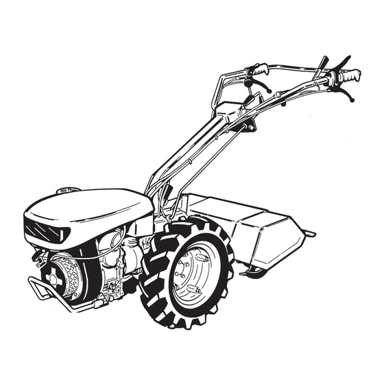
- Page 3 REVERSIBLE TWO-WHEEL TRACTORS REV. 1000 (2+2) REV. 1000 Special (3+2) REV. 1000 Diesel (2+2) REV. 1000 Diesel Special (3+2) REV. 1000 E (2+2) BEFORE USING THE TWO-WHEEL TRACTOR CAREFULLY READ THE INSTRUCTIONS GIVEN IN THIS MANUAL...
-
Page 4: Table Of Contents
TABLE OF CONTENTS Page Page INTRODUCTION............ 3 OPERATING THE TWO-WHEEL TRACTOR..16 STARTING THE ENGINE........16 SAFETY REGULATIONS ........3 STOPPING THE ENGINE ........17 GENERAL NOTICES..........3 STARTING THE ENGINE ........4 FITTING FRONT-MOUNTED ATTACHMENTS..17 OPERATING OF THE TWO-WHEEL TRACTOR ... 4 SAFETY DEVICE .......... -
Page 5: Introduction
INTRODUCTION • This manual provides Use and Maintenance in- specifications and gives instructions relevant to the machine. The second section of the manual structions, technical specifications, and safety pre- cautions for reversible two-wheel tractor: gives further details on individual attachments, and provides all specific operating instructions. -
Page 6: Starting The Engine
OPERATING OF ATTACHMENTS SAFETY DEVICES • Do not use the two-wheel tractor if the safety de- • Check that the attachment coupled to the PTO vices are missing or defective. functions correctly before starting the motor. • Do not interfere with safety devices. •... -
Page 7: Identification Data
− in case of excessive vibrations (investigate cause immediately). • Stop the engine before adjusting attachments. • Periodically check that all nuts and bolts are tight. • Do not leave your two-wheel tractor in closed am- bient with fuel in the tank. Fuel vapour is a potential source of danger. - Page 8 NOISE AND VIBRATIONS TYPE OF MARKING Test conditions: TWO-WHEEL TRACTOR 1000 (2+2) Test conditions: - P.T.O.: Engaged - P.T.O.: Disengaged - machinestationary on a concrete plane surface Sound Acceleration pressure on Acoustic power on hangrip Models: 1000 (2+2) - 1000 Diesel (2+2) operator’s ears dB(A) EN 1033 - 28662/1...
- Page 9 NOISE AND VIBRATIONS TYPE OF MARKING Test conditions: - P.T.O.: Disengaged - machinestationary on a Test conditions: - P.T.O.: Engaged TWO-WHEEL TRACTOR 1000 (2+2) E concrete plane surface Acceleration Sound on hangrip pressure on Acoustic power EN 1033 - 28662/1 operator’s ears Sound dB(A)
- Page 10 NOISE AND VIBRATIONS TYPE OF MARKING Test conditions: - Engine R.P.M.: 85% peak R.P.M. TWO-WHEEL TRACTOR 1000 (3+2) Test conditions: - P.T.O.: Engaged - P.T.O.: Disengaged - machinestationary on a concrete plane surface Sound Acceleration pressure on Acoustic power on hangrip operator’s ears dB(A) EN 1033 - 28662/1...
-
Page 11: Technical Specifications
TECHNICAL SPECIFICATIONS Configuration with front-mounted attachments: 2 for- ward speeds and 2 reverse speeds. ENGINE When the machine is fitted with front-mounted at- tachments, forward speeds become reverse speeds The two-wheel tractor may be fitted with the following and vice versa because of reversal of the direction of engines: motion. -
Page 12: Accessories
NOTE Refer to our catalogue for details about the various The instructions covering track adjustment, based on accessories available. machine model and type of wheel, are given in a spe- cific paragraph in this manual. MASS Refer to the identification plate installed on the ma- ACCESSORIES chine. -
Page 13: Safety Devices
SAFETY DEVICES The two-wheel tractor is fitted with the following safety devices to ensure maximum safety: − Automatic PTO disengagement device. This is a mechanical device that prevents shift into reverse speed when the PTO is rotating (two-wheel tractor configuration only). −... -
Page 14: Transfer Printing - Instructions And Safety
TRANSFER PRINTING - on the machine. For accident prevention purposes, they must always be clearly readable. Should they be INSTRUCTIONS AND SAFETY damaged, it is compulsory to replace them by request- Please find below the adhesive transfer printing shown ing the original spare part from the Manufacturer. -
Page 15: Two-Wheel Tractor Controls
TWO-WHEEL TRACTOR CONTROLS See fig. 4. 8. Throttle control lever. 9. R.H. brake lever (Special versions). 1. Clutch lever. 10. L.H. brake lever (Special versions). 2. Engine stop lever. 11. PTO instant adaptor. 3. Differential lock lever. 4. PTO control lever (Note 1). NOTE 1: When the machine is fitted with front- mounted attachments, this lever becomes 5. - Page 16 Gear lever 3rd speed preselection control lever (two-wheel tractor version Special 3+2) CAUTION The Special version of the two-wheel tractor is fitted When using the machine as a motor mower, the han- with a preselection lever for engagement of the 3rd dlebars must be rotated through 180°.
-
Page 17: Parking Brake
Throttle control lever (See fig. 10) − Lever (1) in up position: engine at idle. − Lever (1) in down position: max engine rpm. Brake levers (Special versions) The brakes act independently on the two wheels, and can be used separately to assist tight cornering as well as together to slow the machine in a straight line. -
Page 18: Controls Of Front-Mounted Attachments
PTO Instant adaptor OPERATING THE This allows attachments to be coupled and de- TWO-WHEEL TRACTOR coupled quickly and easily to and from the PTO. The lever (1) has two positions (see fig. 11): WARNING − Locked position: pull up lever (1). Before operating your two-wheel tractor, read care- −... -
Page 19: Stopping The Engine
g. Lock the clutch lever (2) in position with locking device (3). WARNING h. Turn throttle control lever (4) for 1/4 turn. The engine stop lever (2) also operates as a safety device (emergency stop), and stops the engine as i. -
Page 20: Removal Of 3Rd Speed Preselection Control Lever
REMOVAL OF 3rd SPEED REVERSING THE HANDLEBARS PRESELECTION CONTROL LEVER Rotate the handlebars through 180° to operate the machine in the changed direction of motion. When front-mounted attachments are used, it is nec- Proceed as follows (see fig. 18): essary to remove the 3rd speed preselection control lever from the machine. -
Page 21: Coupling Attachments To The Pto
COUPLING ATTACHMENTS TO Three different adjustments of track are thus possible. THE PTO The PTO is fitted with an instant adaptor device to fit attachments quickly and easily. Proceed as follows to fit your attachments (see fig. 19): a. Check that lever (1) is in “disengaged” position. b. -
Page 22: Maintenance
Wheels (4.00-8) with adjustable track NOTE Filter cleaning frequency depends on operating con- (35-40-45-50 cm) ditions, but should never be more than 8 hours. These wheels have hexagonal axle holes and a hub with two through holes. Every 60 hours To adjust track width, fit wheel (fig. -
Page 23: Power Take Off
Every 20 hours DIFFERENTIAL LOCK LEVER (Special versions) Check the level of the oil in the gearbox. The level must be between the maximum and minimum notch If differential lock lever movement proves insufficient on the dip-stick (1). to fully unlock the differential, adjust the cable by NOTE means of adjuster (fig. -
Page 24: Rotary Tiller
ROTARY TILLER WARNING • Do not use the rotary tiller without the hood. • Do not proceed to tilling in proximity of children and/or animals. • Keep your hands and feet clear of the tiller at- tachment when the motor is running. Stop the en- gine before touching the tiller for any reason. -
Page 25: Rotary Tiller Maintenance
Tilling width adjustment Adjustment of protection guards The adjustable tiller model allows you to set working a. Adjust width of protection guards to suit new tilling widths of 40, 50, 60 cm, to suit the type of crop. width. To do this, remove the screws (fig. 4, item Adjustment of tilling width is obtained by reversing 1), and install the two side extensions (2). - Page 26 Every 300 hours Change the tiller drive unit oil as instructed above.
-
Page 27: Cutter Bar Mower
CUTTER BAR MOWER Light weight and maneuverability make this attach- ment ideal for mowing large areas. WARNING Sickle bar mowers are available in 95 - 110 - 127 cm • When you transport your machine, and when you fin- sizes, while E.S.M. bar mowers are available in 97 - ish work, always fit the knife guard over the cutter 117 cm sizes, and Special type in 115 cm size. -
Page 28: Cutter Bar Mower Technical Specifications
CUTTER BAR MOWER TECHNICAL b. Turn adjuster nut (2) of each wear plate to obtain correct knife movement. SPECIFICATIONS c. Tighten again the two securing nuts (1). Sickle bar mowers − Drive: mechanical con-rod. MOWING BAR E.S.M. type S − Cutting width: 95 cm, 110 cm, 127 cm. NOTE The mowing bar type E.S.M. - Page 29 Cutting height adjustment SICKLE BAR MOWERS SPECIAL type (fig. 6) Proceed as follows to adjust cutting height. a. Loosen the nut (1) that secures each of the two support slides (2) SICKLE BAR MOWERS WITH MIDDLE CUT FINGERS b. Regulate the two support slides (2) until the blade AND ADJUSTABLE SHOES (fig.
-
Page 30: Cutter Bar Mower Maintenance
CUTTER BAR MOWER MAINTENANCE Lubrication After the first 5 hours of work, and subsequently af- ter every 10 hours, grease the mower mechanism at point (1) and (2) as shown in fig. 8. -
Page 31: Ec Certificate Of Conformity
EC Certificate of Conformity according to ECC 89/392 Directives and successive modifications VALPADANA S.p.A. 42018 SAN MARTINO IN RIO (RE) ITALY Declare on their own responsibility, that the machine MOTOCOLTIVATORE with rotary tiller and/or sickle bar mower Brand: S.E.P. Type: 1000 E (2+2) - 1000 (2+2) - 1000 Diesel (2+2) from machine serial n°... - Page 32 VALPADANA S.p.A. ® Società unipersonale appartenente al Gruppo Industriale Argo S.p.A. 42018 S. MARTINO IN RIO (RE) ITALY Via Don Pasquino Borghi, 6 TEL. 0522 73.17.11 - FAX 0522 73.17.31 E-MAIL: infosep@sep.it - http://www.sep.it...
Need help?
Do you have a question about the REV. 1000 (2+2) and is the answer not in the manual?
Questions and answers
How much is the part with the hardy spicer number 1