Table of Contents
Advertisement
Quick Links
Download this manual
See also:
User Manual
USER GUIDE
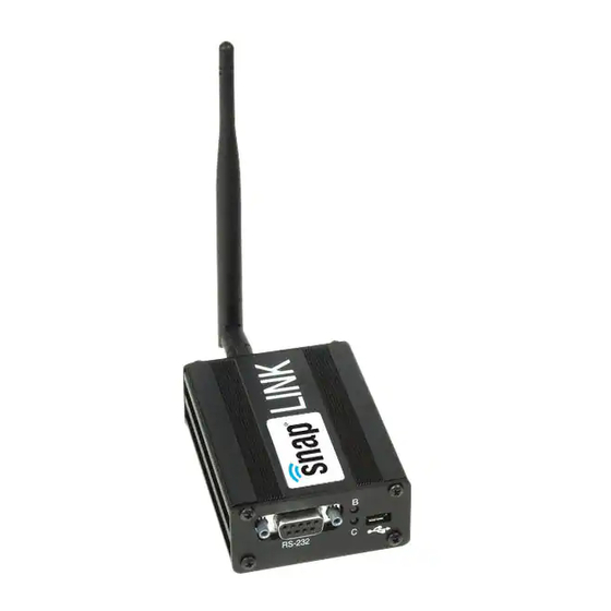
SNAP Link
Serial Wireless Adapter
RS-232 and RS-485 Devices
©2008-2014 Synapse, All Rights Reserved. All Synapse products are patent pending. Synapse, the
Synapse logo, SNAP, and Portal are all registered trademarks of Synapse Wireless, Inc.
Doc# 600038-01D
6723 Odyssey Drive
//
Huntsville, AL 35806
//
(877) 982-7888
//
Synapse-Wireless.com
Advertisement
Table of Contents

Related Manuals for Synapse SNAP Link


Summary of Contents for Synapse SNAP Link
-
Page 1: User Guide
SNAP Link Serial Wireless Adapter RS-232 and RS-485 Devices ©2008-2014 Synapse, All Rights Reserved. All Synapse products are patent pending. Synapse, the Synapse logo, SNAP, and Portal are all registered trademarks of Synapse Wireless, Inc. Doc# 600038-01D 6723 Odyssey Drive... - Page 2 Information contained in this Manual is provided in connection with Synapse products and services and is intended solely to assist its customers. Synapse reserves the right to make changes at any time and without notice. Synapse assumes no liability whatsoever for the contents of this Manual or the redistribution as permitted by the foregoing Limited License.
-
Page 3: Table Of Contents
Table of Contents About Your SNAP Link Wireless Adapters ..............1 Setting Up Your SNAP Link Wireless Adapters ............. 3 Modes of Operation ......................... 3 SNAP Link State Indicators ....................... 3 Changing SNAP Link States ......................4 SNAP Link EasySet Software ..................7 Installing EasySet.......................... -
Page 5: About Your Snap Link Wireless Adapters
Windows®-based computers that allows you to configure the device quickly and easily. Please refer to software specifications in the appendix of this document for exact operating system requirements. You can also configure your SNAP Link adapters using internal DIP switches in the event a computer running EasySet is not available. -
Page 6: Download Supporting Materials
• The micro-B USB port of the SNAP Link adapter may be referred to as simply the USB port. • The term RS-485/422 device or RS-232 device refers to the data communications device you are attaching to the SNAP Link adapter. -
Page 7: Setting Up Your Snap Link Wireless Adapters
You can change the state of your adapter either by holding down the MODE button or by pressing it in rapid succession. There are three LEDs on a SNAP Link device. LED A is located on the front next to the MODE button. LEDs B and C are located on the back panel between the micro-B USB and serial connectors. -
Page 8: Changing Snap Link States
SNAP Link device will be married to, or paired with, another SNAP Link. The factory default serial port settings for all SNAP Link devices is 9600 baud, 8 data bits, no parity, and 1 stop bit. For SL232 devices flow control is disabled, and for SL485 devices flow control is always enabled. The SNAP network ID is set to 0x1C2C and the channel number is set to 4. -
Page 9: Pin Outs
SL232, are defined as a DCE. To connect a DCE with another DCE, or DTE to another DTE, a null modem adapter, or crossover cable, is required. The null modem adapter swaps certain pins, typically pins 2 and 3, and 7 and 8, to convert a DCE into a DTE and vice-versa. SNAP Link... - Page 10 To wire a connection in two-wire mode, pick a pair of TX/RX pins – either 1 and 2 or 3 and 4. If your application requires a ground wire, sometimes referred to as 3-wire or 5-wire, then also include pin 5. SNAP Link...
-
Page 11: Snap Link Easyset Software
SNAP Link EasySet Software Synapse has developed an intuitive software application to help you configure your SNAP Link adapter. This software, known as SNAP EasySet, provides a graphical interface to access settings such as baud rate, flow control, and parity bits. -
Page 12: Using Easyset
Connect a SNAP Link device to your computer using the supplied USB cable. The micro-B side of the cable fits into the back of the SNAP Link device and the USB end fits into any standard USB port on your PC. This connection supplies power to the SNAP Link and also allows EasySet to communicate with it. -
Page 13: Selecting Basic Communications Settings
SNAP Link device. When the SNAP Link device is powered up for the first time, you will see the factory default settings set internally by the DIP switches. Once the configuration is changed by EasySet, the SNAP Link device will retain the new configuration in flash memory. - Page 14 Set the SNAP Link baud rate to match that of your serial device. The baud rate for all devices can range from 0 to 115,200. While K-series adapters can send chunks of data in bursts up to Baud Rate 115,200, they safely sustain a maximum of 19,200 baud.
- Page 15 Mesh routing can be enabled, disabled, or set to custom. Enable mesh routing to allow a SNAP Link device to participate as a node in a wider SNAP mesh network. If you set Mesh Routing to custom, then the maximum age, in milliseconds, can be specified here.
- Page 16 Master’s transmissions. Example: There are four SNAP Link adapters in a long linear line: Master, Client1, Client2 and Client3. Master node transmissions do not get to the farthest Client (3), but it appears Client1 could get it to Client2 and Client2 could get it to Client3 since each Client is about 1/3 of the distance away from its neighbors.
-
Page 17: Uart Settings
Buffering Threshold is reached. Conversely, if the timeouts are high or disabled altogether, then data will be transmitted when the Buffering Threshold is reached. Setting a large Inter-character Timeout can give better multicast transparent mode reliability but with greater latency. SNAP Link... -
Page 18: Pairing Settings
Advanced Settings The Advanced tab contains a single checkbox labelled Button Lockout. When checked, the MODE button on the front of the SNAP Link adapter will be disabled. However, the MODE button can still be used to perform a reset, putting the SNAP Link device back into broadcast state. -
Page 19: Configuring Your Adaptor Using The Dip Switches
4. Configuring your Adaptor using the DIP Switches You use the MODE button on the front panel of your SNAP Link adapter to define which SNAP Link adapters communicate with each other, as discussed in earlier sections of this manual. You use the EasySet software to modify the entire range of parameters, also as discussed in earlier sections of this manual. -
Page 20: Dip Switch 2
2-Wire Half Duplex 4-Wire Half Duplex 4 Wire Full Duplex RS-422 Some device manufacturers might refer to these as 3-wire or 5-wire. This is referring to the same settings described above, but are including the ground wire in their specification. SNAP Link... -
Page 21: Application Usage Scenarios
Buffering Threshold – the minimum number of characters to enqueue before the buffer is transmitted. SNAP Link contains a 123 byte buffer, but that must include a 12 byte header when in multipoint mode and a 15 byte header when in point-to-point mode. The default value is 100. Values over 100 are not recommended, especially at high baud rates, because the buffer could be overrun resulting in dropped... -
Page 22: Scenario 3: Lowest Latency At Highest Baud Rate
• Inter-character Timeout – This parameter should be smaller than the Buffering Timeout to force transmission of very small payloads with pauses between them. In this scenario, set this parameter at about half of the Buffering Timeout setting. SNAP Link... -
Page 23: Troubleshooting
Multiple Masters In a multipoint network, if SNAP Link devices are unable to pair with a master, check for the presence of multiple masters. There can be only one master in a multipoint network. If you wish to operate multiple masters within the same vicinity, then be sure to set each master to a different channel and/or network ID using either EasySet or the DIP... -
Page 24: Poor Performance
EasySet. If you don’t see an occasion blink of the green A LED, then you might have an incorrect setting in baud rate, flow control, stop bits, parity, or flow control. If you have more than two SNAP Link units, confirm that each unit is paired to the desired unit. -
Page 25: Frequently Asked Questions
I need to replace the master SNAP Link unit in a multipoint setup that has been working. Must I reset each device, or can I merely set up the new master? ★... - Page 26 ★ The SNAP Link RS-232 devices use a standard DB9 female connector configured as a DCE. It can be connected to a DTE using a straight through cable. If you need to connect an SL232 to another DCE device, then a null modem adapter, or cross over cable, will be required. See the discussion of RS-232 pin outs for further information.
-
Page 27: Appendix A Mounting Options
Appendix A Mounting Options SNAP Link devices can sit on a table top or be wall mounted using the included mounting brackets. To install the brackets, one of the end panels must be removed and the brackets slid into place. -
Page 28: Appendix B Modbus Firmware
Appendix B Modbus Firmware With the release of EasySet V1.2.3, SNAP Link adapters can load a new version of script firmware to increase the reliability of wireless transmissions, by allowing an automatic number of retransmissions by the Master adapter. This multicast retry feature ensures the master continues to retransmit a command if no response is received due to the original transmission. -
Page 29: Appendix C Advanced Management
Appendix C Advanced Management The SNAP Link EasySet software was designed to set up SNAP Link adapters quickly and easily. However, if you should encounter situations where a more powerful tool is needed, Synapse Wireless offers Portal™, an advanced SNAP network Administration tool, as a free download from the web site. To access the download you will need to register on the Synapse forum site at: forums.synapse-wireless.com/register.php... - Page 30 Type Included External Reverse Polarity SMA connector, omni directional Gain 3.2 dBi Length 5.875 in (14.9 cm) Impedance 50 Ohms unbalanced Certifications FCC Part 15, Class B Power Supply RoHS (lead free) Compliant Energy Star Compliant IC Certification SNAP Link...
- Page 31 2 or 4 wire: ITX+, TX-, RX+, RX-, GND (selectable) Data bit; Parity; Stop bit 7, 8; no parity, even, odd; 1 Software OS Support Microsoft Windows XP (SP2) or Windows 7 Configuration EasySet - Configuration Tool Included SNAP Link...
-
Page 32: Rf Exposure Statement
FCC ID. Modifications (FCC 15.21) Changes or modifications to this equipment not expressly approved by Synapse Wireless, Inc. may void the user’s authority to operate this equipment. - Page 33 The products listed above have been tested at an External Test Laboratory certified per FCC rules and has been found to meet the FCC, Part 15, Emission Limits. Documentation is on file and available from Synapse Wireless, Inc. Industry Canada (IC) certifications This digital apparatus does not exceed the Class B limits for radio noise emissions from digital apparatus set out in the Radio Interference Regulations of the Canadian Department of Communications.
Need help?
Do you have a question about the SNAP Link and is the answer not in the manual?
Questions and answers