Table of Contents
Advertisement
Quick Links
Description
The OTH770 thermostat has been designed for floor heating
systems. It has built-in ground fault protection and an input for
connecting a floor sensor, supplied with the thermostat.
Depending on the mode of application you choose, each thermostat
can be used to control the floor temperature (F mode) or to control
the ambient temperature while keeping the floor temperature within
comfortable and safe limits (AF mode).
Your thermostat has Vacation Mode which can be activated by
connecting an Aube telephone controller (CT240 or CT241) or any
other remote control device equipped with a normally open (NO) dry
contact.
1
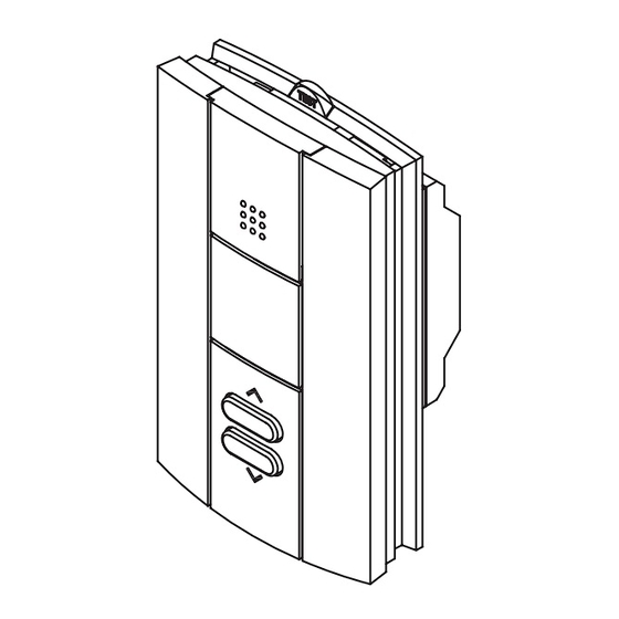
On/Off switch
Appears when
the setpoint
temperature is
displayed
2
Heating intensity
1
Switch the thermostat Off when it is not in use (e.g., during sum-
mer). To reset the ground fault protection, switch the thermostat to
Off and back to On.
2
The image disappears when heating is off.
3
The temperature limits are used only if your thermostat is config-
ured in AF mode.
4
When the ground fault protection is activated, GFI appears on the
screen and the TEST button-light at the top of the thermostat illumi-
nates (see section 7).
OTH770
Floor temperature
3
limit button
Temperature display
On
Off
Floor Limit
Vacation mode indicator
(see section 4)
Ground fault indicator
Temperature adjustment
buttons
Installation
1.
•
Installation must be carried out by a qualified electrician and
must comply with national and local electrical codes.
•
Use this thermostat only for resistive load.
•
Do NOT install the thermostat in an area where it can be
exposed to water or rain.
•
To prevent severe shock or electrocution, always turn the
power OFF at the service panel before working with wiring.
•
Install the thermostat onto an electrical box.
•
This thermostat has tinned copper wires for line and load con-
nections. Use special CO/ALR solderless connectors if you
connect the thermostat to aluminum wires.
Turn off power to the heating system at the service panel in
order to avoid any risk of electrical shock.
To remove the thermostat faceplate, loosen the screw at the bot-
tom of the thermostat and lift the bottom of the faceplate out-
wards towards you. (The screw remains captive on the base.)
4
Connect the thermostat wires to the power supply and to the
load using solderless connectors for copper wires.
240 V (120 V)
L2(N)
L1(L)
OTH770
User Guide
Non-programmable Thermostat
CAUTION
Faceplate
Red
(White)
Red
Black
L2(N)
L1(L)
Red
Red
(White)
Black
400-609-011-A
2009-07-29
2.
Base
Power supply
Black
Black
Load
1/3
Advertisement
Table of Contents

Related Manuals for Ouellet OTH770


Summary of Contents for Ouellet OTH770
-
Page 1: User Guide
Non-programmable Thermostat Installation Description CAUTION The OTH770 thermostat has been designed for floor heating systems. It has built-in ground fault protection and an input for • Installation must be carried out by a qualified electrician and connecting a floor sensor, supplied with the thermostat. -
Page 2: Vacation Mode
To reset the ground fault protection, switch the thermostat to Off and back to On. The TEST button-light will go off. However, if the OTH770 400-609-011-A 2009-07-29... -
Page 3: Technical Specifications
When you press on either of the buttons, the display is lit for 10 OTH770 against defects in material and workmanship for a three (3) seconds. The setpoint appears for 5 seconds, then the actual tem- year period from the date of purchase, under normal use and service, perature is displayed.
Need help?
Do you have a question about the OTH770 and is the answer not in the manual?
Questions and answers