Advertisement
Advertisement

Subscribe to Our Youtube Channel
Summary of Contents for I-AMP GPT 60-IV
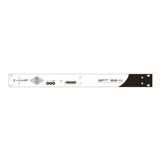
- Page 1 -AMp hEArING LOOp AMpLIFIErs -AMP GPT 60-IV LIN E MA ST ER P O W ER -2 1 -1 5 -1 2 0 d B LEV EL 6 0 V A I N D U C T I O N L O O P A M P L I F I E R...
-
Page 2: Table Of Contents
~ 2 ~ G p t 6 0 - I v Contents Introductory Information Overview of Induction Loop Amplifiers What are Induction Loop Amplifiers? Why do we need to have Induction Loop Amplifiers? How do they Work? Planning the installation - Locating Induction Loops. SETTING THE LOOP OUTPUT CURRENT INSTALLATION RECOMMENDATIONS Practical Constraints on Induction Loop Systems:... -
Page 3: Introductory Information
We are committed to high levels of customer support with engineering advice and design services for the simplest to the most complex of projects. GPT Designs has designed a complete range of induction loop products called the I-AMP range. The I-AMP range includes:... -
Page 4: Overview Of Induction Loop Amplifiers
~ 4 ~ G p t 6 0 - I v Overview of Induction Loop Amplifiers Induction loop systems transmit a signal to the hearing impaired person via baseband electromagnetic waves. One of the greatest advantages of the induction loop system is the ability for the hearing aid to receive the transmitted signal without the use of a separately supplied receiver headset. -
Page 5: What Are Induction Loop Amplifiers
The I-AMP range of induction loop power amplifiers feature a number of internal signal processing functions. These include fast limiters to limit the maximum output current and protect the output electronics... -
Page 6: Planning The Installation - Locating Induction Loops
2. Note that the length of the induction loop cable will increase and the induction loop cable cross sectional area may need to be increased to allow for a maximum DC loop resistance of 1.8Ω. LOOPS OF EQUAL SIZES INDUCTION LOOP AMPLIFIER -AMP GPT 60-IV DESIGnS mAnUFActurinG Excellence Through Engineering... - Page 7 LOOPS OF EQUAL SIZES INDUCTION LOOP AMPLIFIER -AMP GPT 60-IV Double Loops: Some installations require the use of a double loop cable on the output. The double loop is easily implemented with standard figure-8 cables. The double loop increases the field strength for a given output current by 12dB, however the frequency response can suffer.
- Page 8 G p t 6 0 - I v The Venue Master field strength meter (part of the I-AMP range of products) has been designed to allow full frequency response measurement of a induction loop system, allowing compensation of metal loss.
-
Page 9: Setting The Loop Output Current
Audio signals have a wide dynamic range and the peak current requirement can be significantly higher than average. Typically this figure can be taken as around 4 times or 12dB, however this will vary with the input program material. The output current meter on the GPT 60-IV indicates the peak output current of the DESIGnS... -
Page 10: Installation Recommendations
~ 10 ~ G p t 6 0 - I v amplifier. With the internal 2:1 compressor the typical dynamic range will be reduced, reducing the peak current requirements. Peak current requirement (AMPS) Length of one side of a square pick-up area ÷ 2.5 This can be used as a guide to the installation requirements, however the field strength meter should be used to set the final current through the induction loop. - Page 11 ~ 11 ~ G p t 6 0 - I v at the risk of overdriving the telecoil pick-ups in some hearing aids, producing distortion in the received signal. Many installations can be designed to achieve signal to noise ratios of greater than 45dB. Mains wiring is not often a problem over large areas of the induction loop pick-up area since wiring usually constricts the supply and return wires in close proximity to each other, thus limiting the radiated field.
-
Page 12: About Your Induction Loop Amplifier
The GPT 60-IV is housed in a heavy duty standard 1RU rack mount Convection cooled power amplifier with chassis. The unit is designed to be robust and reliable. -
Page 13: Induction Loop Functions
This limiter is not used for reducing the dynamic range of the input signal. The input level control is in circuit before the limiter. Power on Indication LED Output Current Meter. This meter indicates the full range current capability of the GPT 60-IV with the following sensitivities: LED Number... - Page 14 (producing clipping distortion). Note that the gain of the GPT 60-IV is set to provide full output of 4.5 AMPS Peak for a nominal input of +4dBu (Balanced) (1.23 V RMS or 1.74V 0-pk or 3.47V pk-pk) when the input gain is set to 0dB.
- Page 15 ~ 15 ~ G p t 6 0 - I v The current output from the GPT 60-IV may be monitored with a good, high impedance multimeter from the (-) Current Output terminal to ground. This multimeter should have an adequate frequency response for this measurement, typically around 10kHz.
- Page 16 ~ 16 ~ G p t 6 0 - I v DESIGnS mAnUFActurinG Excellence Through Engineering -AMp hEArING LOOp AMpLIFIErs Gpt 300-ii Gpt 60-iv Gpt 20 -AMp hEArING LOOp rECEIVErs VENUE MAstEr VENUE ASSIStANt VENUE listENEr DESIGnS mAnUFActurinG Excellence Through Engineering...
Need help?
Do you have a question about the GPT 60-IV and is the answer not in the manual?
Questions and answers