Table of Contents
Advertisement
Quick Links
Advertisement
Table of Contents

Related Manuals for Apollo SL30


Summary of Contents for Apollo SL30
- Page 1 ® Apollo Model SL30 NAV/COMM Installation Manual February 2002 560-0404-03...
- Page 2 Technologies’s commitment to constantly improve the quality and performance of our products, information contained in this document is subject to change without notice. UPS Aviation Technologies, Apollo, and FlyBrary are registered trademarks of UPS Aviation Technologies Inc. UPS Aviation Technologies Inc.
- Page 3 Source: FAA TSO-C34e, TSO-C36e, TSO-C37d, TSO-C38d, TSO- C40c, TSO-C66c, and TSO-C128. RDERING NFORMATION To receive additional copies of this publication, order part # 560-0404-03, Apollo SL30 NAV/ COMM Installation Manual. EFERENCE UBLICATIONS Following are other publications referenced in this guide.
- Page 4 OTES...
-
Page 5: Table Of Contents
NTENNAS ........................... 16 SE OF PLITTER AND OMBINER ........................17 QUIPMENT NTERFACE ................33 IMITATIONS ON SING A OMPOSITE IGNAL ............33 IMITATIONS ON ISTANCE PEED NFORMATION ....................33 NSTALLATION HECKOUT ........................... 33 OUNTING IRING HECK Apollo SL30 Installation Manual... - Page 6 APPENDIX C - ENVIRONMENTAL QUALIFICATIONS...........55 APPENDIX D - ACCESSORIES ....................57 UPS A ....................57 VIATION ECHNOLOGIES APPENDIX E - SERIAL INTERFACE SPECIFICATIONS ..........59 ..........................59 NPUT OMMANDS ........................59 UTPUT ESSAGES ..........................60 ORMAT ......................60 EFAULT ESSAGE UTPUT ........................60 ESSAGE ORMATS Apollo SL30 Installation Manual...
- Page 7 ............................74 ECEIVER TATUS NAV A ..............................74 UDIO NAV M ..................... 75 ICROCONTROLLER OFTWARE ERSION NAV DSP S ..........................75 OFTWARE ERSION ADC D ............................... 76 UTPUT ..........................76 RANSCEIVER TATUS ............................ 77 OFTWARE ERSION Apollo SL30 Installation Manual...
- Page 8 IGURE OWER AND UDIO ONNECTIONS 10 – SL30 GX50/60 C ..............20 IGURE POLLO ONNECTIONS 11 - SL30 - GX50/60 - MX20 C ..............21 IGURE ONNECTIONS 12 - SL30 NAV MD200-306/307 ..............22 IGURE 13 - SL30 NAV MD200-302/303 C ........23 IGURE...
-
Page 9: Section 1 - Introduction
BOUT ANUAL This manual describes the installation of the Apollo SL30 Nav/Comm units. It is intended for use by persons certified by the Federal Aviation Administration (FAA) to install aircraft navigation devices. It includes installation and checkout procedures for the SL30 unit to standards described in FAA advisory circulars AC 20-67B (for Comm). -
Page 10: Eatures
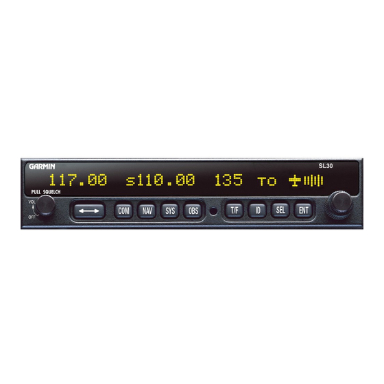
Introduction Figure 1 - SL30 Front Panel EATURES ENERAL EATURES • 32 character high-intensity alphanumeric LED display • Sunlight readable full alphanumeric display • Automatic display intensity • Back-lit buttons • 200 channel memory (stored alphabetically) • Remote frequency flip-flop input pin... -
Page 11: Comm Radio Features
• Input voltage range 10 to 40 VDC • Operating temperature range –20ºC to +55ºC • Transmit power 8 watts (Carrier Power) • Certified TSO C37d (Comm transmitting) • Certified TSO C38d (Comm receiving) • Certified TSO C128 (stuck mic) Apollo SL30 Installation Manual... -
Page 12: System Interfaces
• a speaker or headphone • power input These items may be installed dedicated to the SL30 Comm, or by connection to an audio panel. The system can be configured to mix the NAV audio with the Comm audio if no external audio panel is used. -
Page 13: Npacking The Quipment
ACKAGE ONTENTS As shipped from the UPS Aviation Technologies factory, the Apollo SL30 package includes most items necessary for installation other than supplies normally available at the installation shop, such as wire and cable ties, and required input and output equipment. The standard items included in the package are listed in Table 1. -
Page 14: Other Required Materials
Introduction THER EQUIRED ATERIALS The SL30 is intended for use with standard aviation accessories. External devices required for various installations are listed below. Depending upon the installation, this will include items such as: • back course annunciator • a CDI or HSI •... -
Page 15: License Requirements
ICENSE EQUIREMENTS An aircraft radio station license may be required for operation of the SL30 Comm transmitter once installed in the aircraft. An application must be submitted on FCC Form 404, Form 605 or later revised application, which may be obtained from the FCC in Washington, DC, or any of its field offices. - Page 16 Introduction OTES Apollo SL30 Installation Manual...
-
Page 17: Section 2 - Installation
OUNTING ONSIDERATIONS The SL30 is designed to mount in the avionics stack in the aircraft instrument panel within easy view and reach of the pilot. The standard package includes a mounting frame for ease of mounting, connections, and service of the unit. Allow an additional one-inch clearance to the rear of the mounting frame for connectors and cables. -
Page 18: Equipment Mounting
D ...S1 COS input high E....S3 COS input low F ....S4 SIN input high G ...S2 SIN input low Any electrical zero crossing will work because the SL30 will calibrate out any errors. Glideslope Installation Glideslope installation requires: • SL30 •... -
Page 19: S Pacing
Shims may be necessary to properly install the mounting tube. If the mounting tube is distorted out of square, the unit may either bind when being inserted or the cam lock may not engage. Apollo SL30 Installation Manual... -
Page 20: Unit Insertion
With the cam lock fully disengaged, pull the unit straight out holding onto the sides of the bezel. It is not recommended that you pull the unit out by the rotary knobs. No special extraction tools are required, if the mounting tube is properly installed. Apollo SL30 Installation Manual... - Page 21 Installation Figure 4 - Mounting Frame Assembly Figure 5 - Cable Routing Apollo SL30 Installation Manual...
-
Page 22: Electrical Connections
OWER The SL30 requires two power connections, one for the Nav side of the unit, the other for the Comm. Make the power connections to the unit using 20 awg wire. The Comm power input is internally fused at 7 amps. A separate 5 amp circuit breaker or fuse should be installed for downline overload or short circuit protection. -
Page 23: Microphone Inputs
EMOTE NPUT The SL30 includes a remote flip/flop input. This is an optional input that can be connected to a remote mounted (such as on the yoke) momentary push button switch which pulls the input low to ground. The remote flip/flop input will only toggle the Comm frequencies when Comm frequencies are displayed and will only toggle NAV frequencies when NAV frequencies are displayed. -
Page 24: Use Of Splitter And Combiner
Most VOR/LOC-only antennas will still provide an adequate glideslope signal for the Apollo SL30 to operate normally. In rare cases, it may be necessary to combine antenna signals. When the signals are combined, the systems overall performance may be slightly degraded, but the glideslope signal may increase to an acceptable level. -
Page 25: Equipment Interface
Installations should use an appropriate splitter/combiner, such as the Mini-Circuits ZFSC-2- 1B BNC, available as an option under the UPS Aviation Technologies part number 115-0007. This unit has been fully environmentally qualified for use with single and dual SL30 installations. - Page 26 Installation Figure 7 - SL30 Comm Wiring Diagram Apollo SL30 Installation Manual...
-
Page 27: P Anel C Onnections
Installation Figure 8 - SL30 Comm Typical Audio Panel Connections Apollo SL30 Installation Manual... -
Page 28: C Onnections
Antenna VOR/LOC & GS 1. Nav Audio may be left floating at the SL30. NOTES: 2. Connect shields to designated ground block at the SL10/15. 3. Avionics power leads should use 20 awg wire. All others are specified at 22-24 awg. -
Page 29: Onnections
Installation Figure 11 - SL30 - GX50/60 - MX20 Connections Apollo SL30 Installation Manual... -
Page 30: Md200-306/307
2. Connect cable shields to the mounting frame: pigtails < 1.25 inches 3. Connect shields chassis ground at both ends of each shielded cable 4. Reference the ACU installation manual if installing NAV/GPS source selector Figure 12 - SL30 NAV to Mid-Cont MD200-306/307 Apollo SL30 Installation Manual... -
Page 31: Md200-302/303 C Onnections
2. Connect cable shields to the mounting frame: pigtails < 1.25 inches 3. Connect shields chassis ground at both ends of each shielded cable 4. Reference the ACU installation manual if installing NAV/GPS source selector Figure 13 - SL30 NAV to Mid-Cont MD200-302/303 Connections Apollo SL30 Installation Manual... -
Page 32: Id -C Ont Md200-306/307
Installation Figure 14 - SL30 NAV and ACU to Mid-Cont MD200-306/307 Apollo SL30 Installation Manual... -
Page 33: Onnections
3. Connect shields chassis ground at both ends of each shielded cable 4. Reference the ACU installation manual if installing NAV/GPS source selector. 5. Installer should verify that the STEC IND-351A contains the proper annunciator, i.e., BC backcourse. Figure 15 - SL30 NAV to STEC IND-351A Connections Apollo SL30 Installation Manual... -
Page 34: Kn72/203/204/208/208A/209/209A W Iring
NOTES: 1. Connect shield grounds to aircraft chassis with as short a conductor as practical. 2. Refer to Limitations on Using Composite Signal paragraph in this chapter. 3. Not all indicator connections are shown, only those interfacing to the SL30. Consult the appropriate installation manuals for complete wiring instructions. -
Page 35: Ki202/206/525A/Kpi552 W Iring
NOTES: 1. Connect shield grounds to aircraft chassis with as short a conductor as practical. 2. Not all indicator connections are shown, only those interfacing to the SL30. Consult the appropriate installation manuals for complete wiring instructions. Figure 17 - SL30 NAV to Bendix/King KI202/206/525A/KPI552 Wiring... -
Page 36: C Onnections
5. BC annunciator may be implemented in future software revisions of the SN3308. Refer to Sandel installation manual. 6. Not all indicator connections are shown, only those interfacing to the SL30. Consult the appropriate installation manuals for complete wiring instructions. -
Page 37: Onverter C Onnections
3. Connect shields chassis ground at both ends of each shielded cable. 4. Refer to Limitations on Using a Composite Signal paragraph in this chapter. 5. Not all indicator connections are shown, only those interfacing to the SL30. Consult the appropriate installation manuals for complete wiring instructions. -
Page 38: And Rd650 W Iring
NOTES: 1. Connect shield grounds to aircraft chassis with as short a conductor as practical. 2. Not all indicator connections are shown, only those interfacing to the SL30. Consult the appropriate installation manuals for complete wiring instructions. Figure 20 - SL30 to Sperry RD 550A and RD650 Wiring... -
Page 39: And Pn-101 W Iring
NOTES: 1. Connect shield grounds to aircraft chassis with as short a conductor as practical. 2. Not all indicator connections are shown, only those interfacing to the SL30. Consult the appropriate installation manuals for complete wiring instructions. Figure 21 - SL30 to Collins 331A-6P, 331A-9G, and PN-101 Wiring... -
Page 40: And Nsd 1000 W Iring
NOTES: 1. Connect shield grounds to aircraft chassis with as short a conductor as practical. 2. Not all indicator connections are shown, only those interfacing to the SL30. Consult the appropriate installation manuals for complete wiring instructions. Figure 22 - SL30 to Century NSD 360A and NSD 1000 Wiring... -
Page 41: Imitations On
ETUP AND HECKOUT The SL30 has a built-in I/O test mode to simplify system setup and checkout. To operate the SL30 in the Setup Mode, hold down the ó and SYS buttons while switching on the power. You must continue to hold the buttons in until a complete power up is done and S ELECT is displayed. - Page 42 Installation Indicator Head Type Set up the SL30 for the indicator head type that it is connected to by using the Setup Mode as follows. 1. Rotate the large knob to the S display. ELECT NDICATOR 2. Press SEL. The type will flash.
- Page 43 5. Ensure the flags are reset to all small text when you are finished testing. CDI Test This function tests for CDI function and allows for calibration between the SL30 and the attached CDI. 1. In the Setup Mode, turn the large knob to reach the CDI T page.
- Page 44 NAV flag, and GSI needle GS flag. Some VOR test equipment may not be compatible with the digital signal processing of the Apollo SL30 and will give erroneous results. Examples of equipment known to function properly are: IFR Nav 750 and Collins 479S-6.
-
Page 45: Final System Check
YSTEM HECK The SL30 functions should be complete at this time. The final check includes verifying VOR and ILS operation. Start with the unit turned on and operating in the normal mode. Refer to the user’s manual for operating instructions. -
Page 46: P Erformance
4. Verify that the remote frequencies of the airport selected via the GPS unit are displayed on the SL30. The interface to a DST data source (such as an Apollo GX or DB30) should be checked as follows: 1. Operate the SL30 in NAV mode and ensure the DME is operating with a valid signal. - Page 47 Date: ___/___/___ SL30 P POLLO NSTALLATION HECKOUT By: _____________ ONFIGURATION NFORMATION SL30 NAV/COMM 430-6040-3_____ Mod ____ Serial # ___________ HECKOUT AND ETUP Avionics Outputs: [ ] Resolver [ ] Converter [ ] Serial [ ] None [ ] Calibration (if Resolver)
-
Page 48: Instructions For Continued Airworthiness
NSTRUCTIONS FOR ONTINUED IRWORTHINESS Modification of an aircraft for the installation of the SL30 obligates the aircraft operator to include the maintenance information provided by this section in the operator’s Aircraft Maintenance Manual and the operator’s Aircraft Scheduled Maintenance Program. -
Page 49: Section 3 - Specifications
Weight (without mounting frame).... 2.25 lb. (1.02 kg) NVIRONMENTAL The Apollo SL30 is designed and tested to meet appropriate categories of RTCA/DO-160C and RTCA/DO-160D. The Environmental Qualification Form is included in Appendix C. Operating temperature ......-20°C to +55°C Storage temperature........ -
Page 50: Avionics Outputs
Annunciators ..........Open collector outputs capable of sinking up to 400 mA for turning on annunciator lamps • BC • Localizer Power Control ...........Open collector output capable of sinking up to 50 mA. Active when unit is powered up. Apollo SL30 Installation Manual... -
Page 51: Nav Receiver Performance
Receiver sensitivity ........-115 dBm typical Centering error ......... RTCA DO-195 two sigma limit: 6.6% of full scale SL30 performance: less than 1.0% typical (1.5 mV) Audio output..........With a 1 kHz tone 30% modulation at least 100 mW output into 500 ohm loads Ident/voice .......... -
Page 52: Glideslope
Frequency tolerance ........0.0008% Cross modulation products .......At least 60 dB down Receiver sensitivity........-95 dBm typical Centering error ..........RTCA DO-195 two sigma limit: 6.7% of full scale SL30 performance: less than 2.0% typical (3.0 mV) OBS R ESOLVER TSO compliance........TSO-C40c (DO-196) Applicable documents.......RTCA DO-196... -
Page 53: Comm Receiver Performance
Audio frequency response ......< 4 dB variation with 350 to 2500 Hz, 85% modulation Carrier noise level ........> 35 dB down Sidetone output......... up to 280 mW into 100 Ω, 120 mW into 500 Ω Apollo SL30 Installation Manual... -
Page 54: Intercom Performance
NTENNA EQUIREMENTS NTENNA The Apollo SL30 requires a VHF Comm antenna meeting the following specifications: • Standard 50 Ω vertically polarized antenna with a VSWR < 2.5:1. NAV A NTENNA The Apollo SL30 requires a VHF NAV antenna meeting the following specifications: •... -
Page 55: Serial Interface
Specifications ONNECTOR INOUT The SL30 includes two rear panel connectors, a 15-pin for the Comm interface connections and a 37-pin for the rear panel connections. The pinout for the connectors is listed in the following tables. Table 2 - Comm Interface Connector Pinout... -
Page 56: Specifications
Active low output when a localizer frequency is tuned OBS_G {S2} Resolver return signals G Reserved Do not connect Power control Power control output sinks up to 50 mA when unit is on Ground (comp) VOR/LOC composite ground return Viewed from rear of unit Apollo SL30 Installation Manual... -
Page 57: Section 4 - Limitations
21-Subpart O, FAR Part 21-Subpart K, or other appropriate FAA approved guidelines. When Nav tuning is provided to an Apollo GX, the GX will output Distance, Speed, and Time (DST) information on the MapCom output. It is the installer’s responsibility to ensure that this information is displayed in an acceptable fashion on the Apollo SL30. - Page 58 Limitations OTES Apollo SL30 Installation Manual...
-
Page 59: Appendix A - Troubleshooting
Consult the configuration of the other RS-232 device. Device not compatible, or improper Verify SL30 Rx is connected to connection. remote device Tx and SL30 Tx is connected to remote device Rx. Resolver won’t calibrate. Incompatible resolver or improper Check the resolver specifications and connection. -
Page 60: Contacting The Factory For Assistance
Troubleshooting ONTACTING THE ACTORY FOR SSISTANCE If the Apollo SL30 unit fails to operate despite troubleshooting efforts, contact the UPS Aviation Technologies factory for assistance. UPS Aviation Technologies Inc. 2345 Turner Rd. SE Salem, Oregon 97302 Phone (503) 581-8101 or 1-800-525-6726 Be prepared with the following information about the installation: •... -
Page 61: Appendixb - Periodic Maintenance
. See the operator’s manual for details. HECK QUIPMENT ALIBRATION The SL30 design requires very few adjustments or calibration to be made. In fact, there are no internal manual adjustments. EFERENCE SCILLATOR The reference oscillator frequency should be checked approximately every 3 to 5 years to ensure the units transmit frequency is within allowable tolerance. - Page 62 Periodic Maintenance OTES Apollo SL30 Installation Manual...
-
Page 63: Appendix C - Environmental Qualifications
Environmental Qualifications C - E PPENDIX NVIRONMENTAL UALIFICATIONS The Apollo SL30 Comm module has been tested to the following environmental categories per procedures defined in RTCA/DO-160C. Environmental Qualification Form Model: SL30 Comm portion Manufacturer: Part No: 430-6040-3XX UPS Aviation Technologies Inc. - Page 64 Environmental Qualifications The Apollo SL30 Nav module has been tested to the following environmental categories per procedures defined in RTCA/DO-160D. Environmental Qualification Form Model: SL30 NAV portion Manufacturer: Part No: 430-6040-3XX UPS Aviation Technologies Inc. TSO No: TSO-C34e, TSO-C36e, TSO-C40c, &...
-
Page 65: Appendixd - Accessories
Accessories D - A PPENDIX CCESSORIES This appendix includes information on accessory items available for the Apollo SL30. Refer to the information that is provided with those items for complete specifications and installation instructions. UPS A VIATION ECHNOLOGIES Splitter/Combiner UPS Aviation Technologies Part #: ..115-0007 Manufacturer ........Mini-Circuits... - Page 66 Accessories OTES Apollo SL30 Installation Manual...
-
Page 67: Appendixe - Serial Interface Specifications
• Active COMM frequency • Set Omni-Bearing Select (OBS) value from remote source • DME sensor input UTPUT ESSAGES SL30 output messages include: • Reset status • CDI, GSI, and flags • Decoded OBS setting • Radial from active VOR •... -
Page 68: Data Format
EFAULT ESSAGE UTPUT At system start when the SL30 is configured to operate in normal mode, the following messages will be configured for output at the specified rates: • CDI, VDI, and Flags at 10Hz (high rate). • Decoded OBS Setting at 10Hz (high rate). -
Page 69: Message Definitions
The maximum message length, including the start of message character (“$”) and the end of message <CR><LF> sequence, is 25 bytes. This message format is the same as is used in the SL40 VHF Comm Radio. The SL30 will be able to accept all messages intended for an SL40 without generating a serial communications error. -
Page 70: Remote Vor List
The following two commands work together in allowing remotely connected devices to provide a list of VOR frequencies to the SL30. The remote device will send a sequence of Remote VOR Input commands (message identifier 20). When all of the VOR Input commands have been sent, the remote device should send a Remote VOR List Trailer command (message identifier 21) to terminate the list. - Page 71 Serial Interface Specifications The data consists of five characters for the VOR station identifier followed by two characters defining the VOR frequency. Apollo SL30 Installation Manual...
-
Page 72: Remote Localizer List
The following two commands work together in allowing remotely connected devices to provide a list of localizer frequencies associated with an airport to the SL30. The remote device should first send the Remote Localizer List Header command (message identifier 22), followed by a sequence of Remote Localizer Input commands (message identifier 23). - Page 73 Frequencies used for VORs, which can also be found in the range of 108.10 to 111.95 MHz, will not be accepted in this message type. Example message: $PMRRV2331<Sp><Sp>><<chksm><CR><LF> Identifier is “31 ”, indicating a runway, and the localizer frequency is 110.300 MHz. Apollo SL30 Installation Manual...
-
Page 74: Request Data Output
Serial Interface Specifications EQUEST UTPUT This input is used to request an output message to be sent by the SL30. Message format: “V”....Message class. This is a VHF NAV message. “24”....Message identifier. ii .....Output identifier of requested message, two ASCII characters. -
Page 75: Set Active Vor/Loc Frequency And Receiver Function
This message is used to set the active VOR or Localizer frequency as well as the receiver operating function. The SL30 can detect if the supplied frequency corresponds to a VOR or a Localizer channel, so this command will work for both types of NAV aids. -
Page 76: Set Standby Comm Frequency And Transceiver Function
= 800 kHz. This command would also set the receiver function to monitor, so the receiver would time-multiplex the active and standby VOR channels to track both stations. Note: The SL30 will check input frequencies for validity. An RS-232 serial error message output will be generated if the frequency is invalid. -
Page 77: Set Nav Audio Mode
47h, +30h = 77h, converted to decimal equals 119 for the MHz portion. The KHz portion converts ASCII ‘4’ to 34h, -30h yields 4h, x25KHz steps = 100 kHz. Note: The SL30 will check input frequencies for validity. An RS-232 serial error message output will be generated if the frequency is invalid. -
Page 78: Set Omni -Bearing Select (Obs) Value
ELECT ALUE This message is used to set the OBS value used by the SL30 as the selected radial for computing the course deviation from a VOR. This message will have no effect unless the SL30 is configured to use the internal OBS source, or a serial OBS source. -
Page 79: Output Messages
ESET TATUS This message is sent to indicate to the host that the SL30 is running and ready to accept data on the serial port. It will be sent once upon startup and when requested by the host. Message format: “V”... -
Page 80: Decoded Obs Setting
.....Valid flag. “0” = bearing not valid, “V” = bearing is valid. dddf ....Bearing to a resolution of 1/10 of a degree. ddd = three digit bearing in degrees, ranging from “000” to “359”. f = 1/10 of a degree. Example message: $PMRRV23V1654<chksm><CR><LF> Apollo SL30 Installation Manual... -
Page 81: Radial From Standby Vor
Identifiers are restricted to using ASCII character 0-9 and A-Z. Example message: $PMRRV25VISLE<Sp><chksm><CR><LF> The decoded station identifier is valid and is “ISLE “. Apollo SL30 Installation Manual... -
Page 82: Communications Error
This message is used to output the current NAV audio mode. There are three possible settings for this mode. The first is “OFF”, which suppresses all of the NAV audio. The second is “IDENT”, which will suppress the voice portion of the NAV audio signal and emphasize the Apollo SL30 Installation Manual... -
Page 83: Nav Microcontroller Software Version
“31” ....Message identifier. vvvv....Software version in ASCII e ..... Engineering version flag: “R” = Released version. “E” = Engineering version. Example message: $PMRRV310101R<chksm><CR><LF> NAV DSP software is version 1.01. It is a released version. Apollo SL30 Installation Manual... -
Page 84: Adc Data Output
118 to 136 MHz, 162 (i.e., 76h to 88h, A2h); k = (kHz offset / 25 kHz) + 30h, ranging from 000 to 975 kHz in 25 kHz steps. a......Transceiver status: R = Normal receive M = Monitor receive Apollo SL30 Installation Manual... -
Page 85: Comm Software Version
This message is used to output the version string for the VHF Comm receiver software. Message format: “V” ....Message class. This is a VHF NAV message. “36” ....Message identifier. vvvv....Software version in ASCII Example message: $PMRRV300103<chksm><CR><LF> Comm software is version 1.03. Apollo SL30 Installation Manual... - Page 86 Serial Interface Specifications OTES Apollo SL30 Installation Manual...
Need help?
Do you have a question about the SL30 and is the answer not in the manual?
Questions and answers