
Subscribe to Our Youtube Channel
Related Manuals for Apollo SL40


Summary of Contents for Apollo SL40
- Page 1 ® Apollo Model SL40 VHF COMM Transceiver Field Maintenance Manual PRELIMINARY Draft 3 April, 1997 560-1014-00...
- Page 2 II Morrow Inc. Due to II Morrow’s commitment to constantly improve the quality and performance of our products, information contained in this document is subject to change without notice. II Morrow and Apollo are registered trademarks of II Morrow Inc. II Morrow Inc. 2345 Turner Rd. SE...
- Page 3 Description 4/8/97 Draft 3. RDERING NFORMATION To receive additional copies of this publication, order part # 560-1014, Apollo SL40 VHF COMM Transceiver Field Maintenance Manual. EFERENCE UBLICATIONS Following are other publications referenced in this guide. IPC 610A Acceptability of Electronic Assemblies...
- Page 4 OTES...
-
Page 5: Table Of Contents
) ......................16 RANSMITTER SIGNAL TO NOISE RATIO ........................... 17 RANSMITTER AUDIO DISTORTION RECEIVER............................ 17 ............................18 ECEIVER ERFORMANCE SPEAKER AUDIO TEST............................18 RECEIVER SENSITIVITY ........................... 19 ....................20 ISASSEMBLY EASSEMBLY ................................. 20 ISASSEMBLY ................................21 EASSEMBLY Apollo SL40 Field Maintenance Manual... - Page 6 2. T ....................11 IGURE ETUP IAGRAM 3. E ....................11 IGURE QUIPMENT ONNECTION 4. T .................... 14 IGURE RANSMITTER ETUP 5. R ....................19 IGURE ECEIVER ETUP 6. C ..................20 IGURE OARD UTLINE Apollo SL40 Field Maintenance Manual...
-
Page 7: Section 1 - Introduction
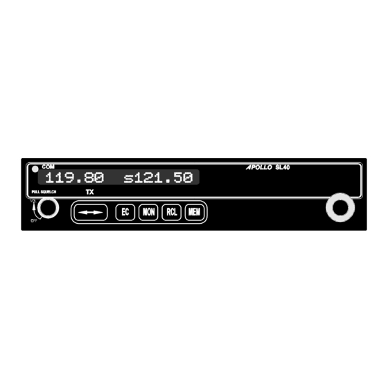
SL40 D POLLO ESCRIPTION The Apollo SL40 is a 760 channel VHF Comm transceiver. It is one member of the Apollo slimline series which includes the SL40 Comm, the SL50 GPS, and the SL60 GPS/Comm. EATURES The features of the SL40 Comm include: •... -
Page 8: Regulatory Compliance
ESD P ROTECTION The case on the SL40 is designed to protect the components from mechanical damage and also provides protection from damage due to electrostatic discharge. Open the case only when the unit is in an ESD safe work area. Observe proper ESD techniques when working on the unit. -
Page 9: Component Handling
SL40. All test equipment must be calibrated before performing the test procedures in this manual. OOLS A 3/32” hex tool is required to remove the SL40 from the mounting frame in the aircraft. A #2 Phillips screwdriver is required for disassembly EST EQUIPMENT a. - Page 10 Introduction OTES Apollo SL40 Field Maintenance Manual...
-
Page 11: Section 2 - Troubleshooting
ESDS components, the circuit boards must be removed from the SL40 and handled in an ESD safe work area only. The work area must comply with the requirements of IPC 610A or other equivalent document. At a minimum, observe the following the following precautions when handling SL40 components. -
Page 12: System Functions
This function is used to display the noise level of the received audio. NOISE With a dummy antenna connected, this function will normally be in the range 162 to 170. Full transceiver functions are operational during this function, including transmit. Apollo SL40 Field Maintenance Manual... -
Page 13: Headphone Level Display And Adjustment
This function is used to display and adjust the sidetone audio level. Turning the small knob changes the value. Setting the value to 0 slaves the sidetone audio level to the volume control knob. Setting to a non-zero value gives a fixed sidetone audio level. SidLv Apollo SL40 Field Maintenance Manual... -
Page 14: Base Station Lockout Mode Display And Adjustment
While viewing the frequency display, use the large and small knobs on the right side of the SL40 to select an unused local channel. Toggle this frequency to the active channel. Press and hold the MON button for about 3 seconds to reach the System Function. Use... -
Page 15: Test Mode Operation
PERATION The test mode allows the SL40 display and controls to be tested with the unit still mounted in the aircraft. The test mode is also used to access certain test and calibration functions used during manufacture and at the service center. -
Page 16: Controls Test Function
It is tested by default by selecting the LARGE various test functions. ETUP A schematic of the SL40 transceiver test setup is shown in Figure 2. Figure 3 is a graphic presentation of the recommended equipment connected for test. Apollo SL40 Field Maintenance Manual... -
Page 17: Figure 2. Test Setup Diagram
Troubleshooting Figure 2. Test Setup Diagram Figure 3. Equipment Connection Apollo SL40 Field Maintenance Manual... -
Page 18: Equipment Tests
QUIPMENT ESTS The tests in the following paragraphs will isolate an SL40 problem to the Com Main board level. If the unit fails any of the tests in either the Transmitter or Receiver sections, refer to the Disassembly/Reassembly procedures on Page 22 for instructions on removing the faulty component. -
Page 19: Transmitter
REQUENCY ERROR Transmitter Frequency error is measured using the HP 8920. This is accomplished by presetting the SL40 to the same channel as the HP8920 and reading the frequency error from the HP8920 Communications Test Set. NOTE: Set the DC supply voltage to 13.75 volts ± 0.75 volts prior to performance evaluating the transmitter. -
Page 20: Ransmitter Ower Easurement
AF GEN LVL NOTE: Where interference may be a problem, use any unused channel for both the SL40 and the HP 8920 as long as both are on the same frequency. A frequency close to center of operating range is preferred. -
Page 21: Transmitter Modulation
Transmitter modulation is measured using the HP8920. This is accomplished by presetting the SL40 to the same channel as the HP8920; inputting a 1000 Hz tone at 50 to 100 mV at MIC 1 and/or MIC 2; and reading the transmitter percentage of modulation from the HP8920 Communications Test Set. -
Page 22: Transmitter Snr ( Signal To Noise Ratio )
RANSMITTER SIGNAL TO NOISE RATIO SNR is measured using the HP8920. This is accomplished by presetting the SL40 to the same channel as the HP8920. Adjust the amplitude of a 1000 Hz tone (input to MIC 1 and/or MIC 2) to obtain 85% modulation. Select the SNR function and the HP8920 Communications Test Set will perform this test automatically. -
Page 23: Transmitter Audio Distortion
Transmitter audio distortion is measured using the HP8920. This is accomplished by presetting the SL40 to the same channel as the HP8920. Adjust the amplitude of a 1000 Hz tone (input to MIC 1 and/or MIC 2) to obtain 85% modulation. Then select the audio distortion function on the HP8920 Communications Test Set. -
Page 24: Receiver
AC LEVEL units to Watts 2. Connect the speaker load to the HP8920 audio in. Turn the SL40 volume control to show an output level of 12 watts on the HP8920. Record the Speaker 1000 Hz Distortion at 12 watts. Value should be < 5%. Set the distortion level to Reference 3. -
Page 25: Receiver Sensitivity
2. Connect speaker load to the HP8920 audio in. Set SINAD low level to 4 dB (LO=4). Turn SL40 volume control until AC LEVEL on HP8920 reads 12 watts. 3. The distortion level on the HP8920 should be < 5%. -
Page 26: Unit Disassembly / Reassembly
Troubleshooting ISASSEMBLY EASSEMBLY ISASSEMBLY Perform the procedures in the following paragraphs to disassemble the SL40. All disassembly must be performed in an ESD safe work area (see guidelines on Page 5) using ESD safe working techniques. Com Main Board Removal 1. -
Page 27: Reassembly
7. Reconnect the ribbon cable from the display board to J603 on the Com Main board. 8. Tilt the SL40 cover so the front edge slides under the tab on the display bezel, and position the cover so the screw holes are aligned with the PEM nuts. Secure the cover with nine 4-40x3/16”... -
Page 28: Eplaceable Omponents
Troubleshooting 3. Tilt the SL40 cover so the front edge slides under the tab on the display bezel, and position the cover so the screw holes are aligned with the PEM nuts. Secure the cover with nine 4-40x3/16” flat head screws. - Page 29 • Installation configuration (accessories, antenna, ...) • Model number, part number with mod levels, and serial number • Software versions • Description of problem • Efforts made to isolate the problem • other installed avionics Apollo SL40 Field Maintenance Manual...
- Page 30 Troubleshooting OTES Apollo SL40 Field Maintenance Manual...
-
Page 31: Section 3 - Checkout Procedures
ROCEDURES ENERAL This Section provides procedures for final verification and checkout of the SL40 prior to returning the unit to service. During the checkout, the Test Data Sheet described in Appendix A is to be filled out. If all items check out properly, the unit may be reinstalled in the aircraft and returned to service. - Page 32 Checkout Procedures OTES Apollo SL40 Field Maintenance Manual...
-
Page 33: Appendixa - Test Data Log
Once the unit is repaired and the checkout procedure on Page 25has been performed to verify proper operation, reinstall the SL40 in the aircraft. Refer to the SL40 Installation Guide, 560-0956 for installation instructions. The steps that are not applicable to a particular installation may be skipped. - Page 34 MHz (≥ 35dB) Transmitter Audio Distortion MHz (< 10%) ECEIVER HECKOUT Speaker Audio Distortion % (< 5%) Receiver Sensitivity: Distortion % (<5%) Headset Audio Distortion % (< 5%) Noise dB (≥ 25dB) Ampl. µvolts (<1µv) OMMENTS OTES Apollo SL40 Field Maintenance Manual...
Need help?
Do you have a question about the SL40 and is the answer not in the manual?
Questions and answers