Epson LX 810 Service Manual
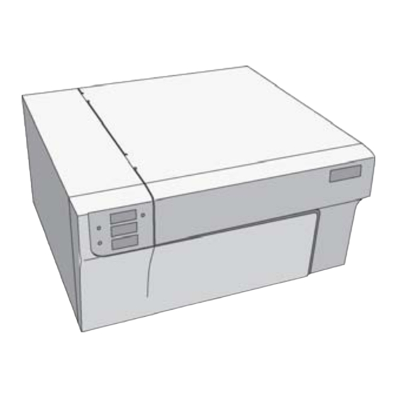
Color label printer
Hide thumbs
Also See for LX 810:
- User manual (313 pages) ,
- Technical manual (176 pages) ,
- Manual (8 pages)
Table of Contents
Advertisement
Quick Links
SERVICE MANUAL
Introduction
This manual details the steps necessary to replace many components on the LX810. It is not intended to
be a comprehensive manual for replacing all parts on the LX810. Instead it is broken down into modules or
assemblies. The manual explains how to replace the entire assembly, not specific parts on each assembly.
The assemblies included in the manual are the ones most likely to be damaged or need replacement after
extensive use.
You will need only a few tools to complete these repairs. A T10 Torx screwdriver, a Phillips #1 screwdriver
and a straight screwdriver are required. Long shank screwdrivers work best. For ease of use, the
screwdrivers should be magnetized.
Section
1. Removing the Top Cover ................................................................................................... 2
2. Replacing the Printer Module .............................................................................................. 4
3. Removing the Front Cover................................................................................................... 12
4. Replacing the Label Clamp Assembly.................................................................................... 14
5. Replacing the Ink Pads....................................................................................................... 18
A. Replacing the Center Air Filter.................................................................................... 18
B. Replacing the left and right side Ink Pads..................................................................... 19
6. Replacing the Feed Motor................................................................................................... 21
7. Replacing the Main Board................................................................................................... 23
8. Replacing the Loop Sensor.................................................................................................. 25
9. Removing a Jam in the Label Sensor................................................................................... 26
Appendix A - Parts List........................................................................................................ 27
- 1 -
Page
Advertisement
Table of Contents

Related Manuals for Epson LX 810


Summary of Contents for Epson LX 810
-
Page 1: Table Of Contents
SERVICE MANUAL Introduction This manual details the steps necessary to replace many components on the LX810. It is not intended to be a comprehensive manual for replacing all parts on the LX810. Instead it is broken down into modules or assemblies. -
Page 2: Removing The Top Cover
Section 1: Removing the Top Cover 1. Open the Top Cover. 2. Remove two Phillips Head screws as shown. 3. Close the Top Cover. 4. Remove two Phillips Head screws as shown. 5. Pull the Top Cover back until you see a gap as shown. - Page 3 6. Open the Top Cover. 7. Grab the cover by the bottom and tilt it upward. 8. Pull the cover from the base. - 3 -...
-
Page 4: Replacing The Printer Module
Section 2: Replacing the Print Module • Part Number 660200 1. Remove the Top Cover. Refer to Section 1 instructions. 2. Remove two T10 Torx screws as shown. 3. Remove the USB Cable from the Main Board. 4. Remove three Phillips screws as shown. 5. - Page 5 7. Remove two screws from the Star Wheel Plate Assembly. 8. Remove the Assembly. 9. Remove three T10 torx screws from Upper Clamp Plate. 10. Remove Upper Clamp Plate. 11. Remove Exit Shaft. - 5 -...
- Page 6 12. Use a flat screwdriver to gently pry the shaft up enough to grab it with your finger (Step 12). 13. Grab the shaft with your left hand. 14. Press down on the far right side of the shaft with your right hand and pull up and to the left in the middle until the shaft is free from its mounting holes.
- Page 7 16. Disconnect the connections J14 (Lex Power) and J5 (Lex Ctrl) from the main board. 17. Remove J14 and J5 wires from the wire harness. 18. Remove the motor wires from the wire harness. - 7 -...
- Page 8 19. Move the print carriage to the middle of the print area to access the print module screws. 20. Remove right Print Module mount screw. 21. Loosen this screw. (This step is not necessary for units with Serial Numbers greater than 2050300000) - 8 -...
- Page 9 22. Remove two left side mount screws. 23. Slide the module forward slightly and tip the front portion up in order to remove it from the printer. The parts shown to the right were removed and should be reinstalled in reverse order. Note: Print Module is shown with metal Board Cover removed.
- Page 10 Screw Notch. Right Side Tab. Left Side Notched Pin. Right Side Tab. - 10 -...
- Page 11 When replacing the exit shaft, you will need to hook the notched edge of the shaft into the belt before snapping the roller back into place. Notched side should be installed to the left. - 11 -...
-
Page 12: Removing The
Section 3: Removing the Front Cover Removing the Front cover is necessary to access the Label Clamping Assembly and to replace the left and right ink pads. 1. Remove the Top Cover (Refer to Section 2. Remove two T10 Torx screws. 3. - Page 13 5. Loosen the bottom Phillips head screw which is attached to the Front Cover from behind. Note: When replacing this screw, do not over tighten! Over tightening will result in problems replacing the Top Cover. 6. Disconnect J1 (Frnt Panel) from the main board. 7.
-
Page 14: Replacing The Label Clamp Assembly
Section 4: Replacing the Label Clamp Assembly • Part Number 660030 1. Remove the Front Cover (Refer to Section 3 for Instructions) 2. The label Clamp Assembly is secured by four T10 Torx screws. 3. Remove the two right side torx screws. 4. - Page 15 5. Disconnect J18 (Label Clamp Sensor) and J2 (Label Clamp Motor) from the Main Board. 6. Tip the Label Clamp Assembly forward. 7. Pull the Assembly up and out and set it on the table. 8. Remove the wires from the unit by feeding the main board connections through the hole in the metal frame.
- Page 16 9. Locate the new label clamp assembly. 10. Feed the connectors through the hole in the metal frame. (Put the wires back into the wire harness) 11. Set the Assembly in place as shown. 12. Tip the Assembly up and partially into place. 13.
- Page 17 14. To complete the installation, snap the metal tabs under the metal roller guide. 15. When reconnecting wires to the main board make sure J2 (Label Clamp Motor) is correctly connected. It is possible to reconnect it up side down causing the clamp to be on when it should be off.
-
Page 18: Replacing The Ink Pads
Section 5: Replacing the Ink Pads • Part Number 074220 (Contains Right and Left Side Pads and Center Air Filter Pad) A. Replacing the Center Air Filter Pad 1. Turn the printer on its side so you can access the bottom. -
Page 19: Replacing The Left And Right Side Ink Pads
5. Place the new filter in the slot. 6. Replace the Air Filter Holder. 7. Replace the screws. B. Replacing the left and right side pads. The left and right side ink pads come in a kit with the Center Air Filter. The pads are shown on the right. It is possible to install the left and right side pads by removing the air filter frame (Section 5A) and blindly removing them from the pins on the base of the unit. - Page 20 2. Place the new pads over the pins. The pads have holes that correspond to the pins. 3. A correctly installed ink pad is shown on the right. - 20 -...
-
Page 21: Replacing The Feed Motor
Section 6: Replacing the Feed Motor • Part Number 660101 1. Remove the Top Cover as described in Section 2. Locate the Feed Motor on the left side of the unit above the main board. 3. Remove Power from the main board. 4. - Page 22 6. Install the new motor. 7. Hook the pulley back into the belt. 8. Replace the Motor Mount Screws. 9. Loosen three Motor Bracket Mount screws ¾ turn each. Twist the motor assembly free and then allow the spring to tension the belt. Retighten screws starting with the lower right and proceeding in a clockwise direction.
-
Page 23: Replacing The Main Board
Section 7: Replacing the Main Board • Part Number 140400 1. Remove Top Cover (Refer to Instructions in Section 2. Remove all connections from the main board. TIP: It may be helpful to label the loose connectors with the Junction letter codes. (Example - J18) 3. - Page 24 5. Locate the new main board. 6. Reattach the connections. Note: All of the wire connectors can only be correctly seated in one connection on the main board. Each connector type as a different number of pins. The 4 white connectors fit on the short pins The 5 blue connectors fit on the long pins.
-
Page 25: Replacing The Loop Sensor
Section 8: Replacing the Loop Sensor • Part Number 140402,140403 1. Remove the Top Cover (See section 1 Instructions). 2. Disconnect the Label Loop Sensor (J19) connector from the main board. 3. Disconnect the Loop LED (J20) connector from the main board. -
Page 26: Removing A Jam In The Label Sensor
Section 9: Removing a Jam in the Label Sensor 1. Remove the Top Cover (Refer to Section 1 Instructions). 2. Remove the Printer Module (Refer to Section 2 Instructions). 3. Remove the two T10 torx screws to access the area under the label sensor. -
Page 27: Appendix A - Parts List
Appendix A - Parts List Part Number Description Price 074220 Kit-LX810 Ink Pad Replacement $12.32 660200 Module-LX810 Replacement Printer $310.44 660030 Assembly - Label Clamp $217.62 660101 Assembly - Feed Motor $113.04 660314 Roller-Label Feed $95.28 140400 LX810 Main Board $213.30 140403 LX810 Loop Sensor...
Need help?
Do you have a question about the LX 810 and is the answer not in the manual?
Questions and answers