Table of Contents
Advertisement
Advertisement
Table of Contents

Related Manuals for GE Interlogix KTC-510

Summary of Contents for GE Interlogix KTC-510
- Page 1 KTC-510/515/540E B/W and KTC-810C/815C/840CE Color Cameras...
- Page 2 © 2003 Kalatel, a GE Interlogix company All Rights Reserved. Any GE Interlogix, Kalatel division, software This equipment has been tested and supplied with GE Interlogix, Kalatel division, found to comply with the limits for a products is proprietary and furnished under...
-
Page 3: Table Of Contents
KTC-510/515/540C/810C/815C/840CE Table of Contents ABLE OF ONTENTS ..............4 EFORE EGIN ................5 ETUP 1.1 S DIP S .........8 ETTING THE WITCH 1.1.1 White Balance (ATW/AWB)..........9 1.1.2 Backlight Compensation (BLC ON)......9 1.1.3 Gamma Correction (r = .45 / r = 1) .......9 1.1.4 Synchronization (L-LOCK/INT)........10... -
Page 4: Before You Begin
For assistance in installing, operating, maintaining, and troubleshooting this product, refer to this document and any other documentation provided. If you still have questions, contact Kalatel Technical Support: GE Interlogix, Kalatel division Call: 800-469-1676 Fax: 541-752-9096 Note: You should be at the equipment, ready with details before calling Technical Support. -
Page 5: Setup
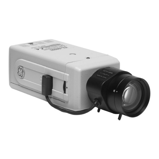
KTC-510/515/540C/810C/815C/840CE Setup ETUP WARNING: Do not expose the unit to moisture. Slide out for Mounting control panel threads (2) Iris lens plug Control Iris connector Back focus Thumbwheel panel thumbwheel locking screw and provided screwdriver Figure 1. Parts of the camera Note: Lens not included. - Page 6 Setup KTC-510/515/540C/810C/815C/840CE To set up the camera, see Figure 2 and perform the following: Note: For back focus instructions, see section 3, Additional Adjustments. Phase adjust DIP switch buttons DD level Lens mode switch Figure 2. Camera controls If you are using a C-mount lens, screw on the C-mount adapter.
- Page 7 KTC-510/515/540C/810C/815C/840CE Setup Note: Figure 4 and Figure 5 show connections for the pins on the solder side of the lens plug. • For auto iris lens with built-in EE amp, follow NC (no (9 VAC the connections in connection) power) Figure 4.
-
Page 8: Setting The Dip Switch
Setup KTC-510/515/540C/810C/815C/840CE DIP S ETTING THE WITCH Set the DIP switch for your camera situation (see Figure 6 and Table 1). Color cameras B/W cameras Figure 6. DIP switches for color and B/W cameras Table 1. DIP switch settings ATW/AWB Auto-tracking white balance / auto white balance Note: ATW/AWB is for color cameras only. -
Page 9: White Balance (Atw/Awb)
KTC-510/515/540C/810C/815C/840CE Setup 1.1.1 (ATW/AWB) HITE ALANCE ATW mode (default) In the ATW mode, the color temperature is being monitored continuously, and the white balance is set automatically by an internal micro-controller. The operating color temperature range is from 2500 to 9500 K. -
Page 10: Synchronization (L-Lock/Int)
Setup KTC-510/515/540C/810C/815C/840CE 1.1.4 (L-LOCK/INT) YNCHRONIZATION Line-Lock (external) (default) The sync pulses are referenced to the supply frequency. The phase adjust buttons are used to synchronize cameras even when they are connected to different phases of the mains supply, which results in roll-... -
Page 11: Connections
KTC-510/515/540C/810C/815C/840CE Connections ONNECTIONS See Figure 7 and perform the following: To local or test monitor To power supply monitor Power LED Figure 7. Back panel connections Attach the monitor’s video in BNC connector to the camera’s VIDEO OUT connector. With a screwdriver, loosen the ~AC24V/DC12V and the GND terminal connectors on the terminal block. -
Page 12: Additional Adjustments
Additional Adjustments KTC-510/515/540C/810C/815C/840CE DDITIONAL DJUSTMENTS OCUS HUMBWHEEL Back focusing is used to match the lens’ back focal length with the camera’s imaging device. It enables the camera to be focused correctly during setup and ensures that the image remains sharp and crisp under various lighting conditions, taking into account changes in the lens’... -
Page 13: Dd Level ( For Dc- Type Lenses )
KTC-510/515/540C/810C/815C/840CE Additional Adjustments DD L EVEL TYPE LENSES When the lens mode switch is set to DD, you can set the lens iris level adjustment to ensure the correct exposure depending on the camera’s position and the lighting levels. (See Figure 2.) -
Page 14: Troubleshooting
Troubleshooting KTC-510/515/540C/810C/815C/840CE ROUBLESHOOTING Problem Probable Cause Solution No picture on the Lens cap is still in Remove the lens cap monitor place No power to the Check that the power camera LED at the camera is lit If the LED is not lit, check... - Page 15 KTC-510/515/540C/810C/815C/840CE Troubleshooting Picture quality is poor Camera lens is dirty Clean the camera lens Monitor is not set up Ensure that the monitor properly settings are correct Ensure that termination at the monitor is correct Confirm that the cable between the camera and...
Need help?
Do you have a question about the KTC-510 and is the answer not in the manual?
Questions and answers