
Subscribe to Our Youtube Channel
Related Manuals for Teltonika WirelessCOM/G10

Summary of Contents for Teltonika WirelessCOM/G10
-
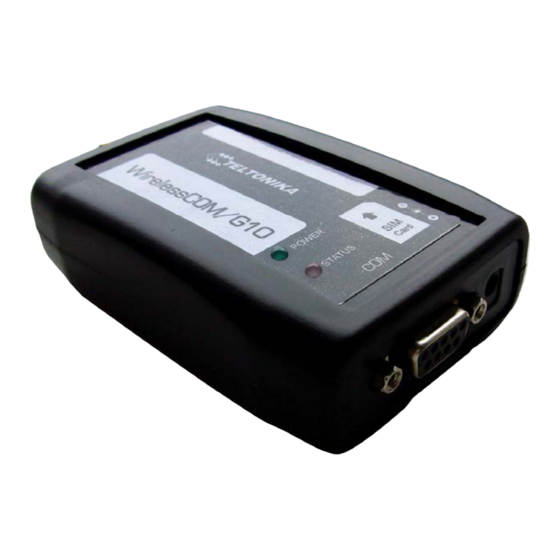
Page 1: Teltonika Wirelesscom/G10
Teltonika WirelessCOM/G10 User’s Manual 4.0.1 Address: Žirmūnų g. 27, Vilnius LT-09105, Tel.: +370 5 2127472, Fax: +3705 276 1380, E-mail: info@teltonika.lt... -
Page 2: Table Of Contents
3.4 Acronyms........................... 5 PACKAGE CONTENTS ......................6 FEATURES ..........................7 INTRODUCTION ........................8 6.1 Wired Solution........................... 9 6.2 Wireless solution using WirelessCom/G10................10 CONFIGURATION ........................11 7.1 Preparing WirelessCOM/G10 configuration ................11 7.2 PC setup........................... 11 7.3 Entering into configuration mode.................... 12 7.4 Command set ........................... -
Page 3: Attention
1. ATTENTION All wireless devices for data transferring are susceptible to interference, which could affect performance Only qualified personnel may install or repair this product The device is not water-resistant. Keep it dry. Do not mount or serve device during a thunderbolt. -
Page 4: Safety Measures
2. SAFETY MEASURES This section will provide guidelines on how to use WirelessCOM/G10 device safely. We suggest you to adhere to following recommendations so as to avoid any damage to person or property. You have to be familiar with the safety requirements before you start using the device! -
Page 5: Basic Information
3. BASIC INFORMATION 3.1 About this document This manual describes the Teltonika WirelessCOM/G10 hardware, configuration and operation. The manual would help the users to deploy, configure and operate WirelessCOM/G10. 3.2 Legal Notice Copyright © 2007 TELTONIKA Ltd. All rights reserved. Reproduction, transfer, distribution or storage of part or all of the contents in this document in any form without the prior written permission of TELTONIKA Ltd is prohibited. -
Page 6: Package Contents
4. PACKAGE CONTENTS Teltonika WirelessCOM/G10 is packed in a box and contains all the accessories required for normal operation: WirelessCOM/G10. AC/DC adapter. RS232 serial cable. External GSM antenna. CD with User Manual. Leaflet “Quick Start Guide”. Note: The manufacturer does not supply the SIM card, which is mandatory for setting up a... -
Page 7: Features
5. FEATURES • Provides transparent GPRS/CSD connection • Receive SMS alerts when exceptions occur in device • No drivers required, hence works with any device/machine/equipment/computer • Simple and informative configuration menu • Configurable through any terminal software • Hardware reset from DTR pin (optional) •... -
Page 8: Introduction
All you need is a device which has a serial port, and WirelessCom/G10. Just configure and connect WirelessCom/G10 to your device/machine and your device/machine would easily turn it into a device which can be accessed from any remotely located server. -
Page 9: Wired Solution
established/CSD call was not answered, you would receive SMS indicating the errors and the concerned parameters. Once configured, connect (physically) WirelessCom to the serial port of your remote device/machine and you would be able to access your device remotely through GPRS/CSD. Additionally, if you want to change the configuration parameters of WirelessCom you can do it remotely using GPRS/CSD/SMS. -
Page 10: Wireless Solution Using Wirelesscom/G10
6.2 Wireless solution using WirelessCom/G10 A typical setup may look as shown in figure 6.2, WirelessCom may be connected (physically) to any device, machine (which has a RS232 port) located in a remote place and the server computer would be present at the company/home. Through various parameters settings (server ip, server port, apn……) present in WirelessCom, it would be configured to connect to the server. -
Page 11: Configuration
1. Insert a GPRS enabled SIM card into WirelessCOM/G10. 2. Connect the physical serial port of WirelessCOM/G10 with COM port of PC (or other device), using a usual RS232 cable. (If you want to configure do not turn ON WirelessCOM/G10 yet) * For initial configuration disable PIN query of your SIM card (If active) 7.2 PC setup... -
Page 12: Entering Into Configuration Mode
Firmware version: xx.xx.xx” appears. LED will blink green and yellow alternately to indicate configuration mode. * Once WirelessCom/G10 is powered-up, for the initial 8 seconds it is waiting to see if user wants to enter into configuration mode or not. Once these 8 seconds are elapsed you cannot enter configuration mode, you would need to restart the device. - Page 13 3) test: Once you have configured all the necessary parameters, you can use this command to check if the settings are fine and if WirelessCOM/G10 is able to make connections using GPRS/CSD bearer. If test is used for CSD bearer, WirelessCOM/G10 will try to connect to the number configured in csd_phone.
- Page 14 7) puk: If you have a sim card with enabled puk, WirelessCOM/G10 gives you the possibility to enter the puk (of sim card) automatically each time the device restarts.
-
Page 15: Configuration Parameters
7.5 Configuration parameters The table below explains all the configuration parameters, with their syntax and description. Parameter Syntax Description Slave mode means that the device is always online and waiting for TCP/CSD connection. In order to reach device in this mode you would need to insert a sim card with static IP. - Page 16 16. SERVER PORT set server_port xxx 0 to 65535. decides time which WirelessCOM/G10 should try to connect to a server (GPRS) or make a call (CSD). set bearer_retry_timeout BEARER RETRY Value (in seconds) should be from 0 to TIMEOUT 300. If the value is “0”, then the device get bearer_retry_timeout keeps trying infinitely.
- Page 17 GPRS server could not be created; CSD connection failed; CSD call was not answered. This parameter is used to set the real time clock of WirelessCom/G10. It is a 24 set clock xx:xx 25. CLOCK hours clock. Valid values are from 00:00...
-
Page 18: Configuration Through Gprs And Csd
GPRS or CSD connection between WirelessCom/G10 and the PC. All the commands (except test) and configuration parameters are supported. Configuration through GPRS/CSD will be the same as if you were directly connected to WirelessCom/G10. However there is one change, every command should start with * and finish with #. -
Page 19: Configuration Through Sms
*get autoconnect# Table 7.2 WirelessCOM/G10 configuration through CSD and GPRS * Changes in mode, bearer will take place only after you will restart the WirelessCom/G10. It is possible to restart WirelessCom/G10 remotely by using the command *restart#. We recommend you to check all the settings and restart WirelessCom/G10 after you are done with remote configuration. -
Page 20: Sms Details
An SMS can include single parameter or multiple parameters. When multiple parameters are to be configured separate them with spaces. You don’t need to include “set” after every parameter. Just type the parameters you want to configure along with their corresponding values and end the message with “set”. -
Page 21: Sms Formats
Table 7.4: Parameters and their short form in SMS 7.8 SMS formats Authorized users can send SMS to WirelessCom/G10 to get information about configuration parameters. There are 2 commands to which would WirelessCom/G10 would reply, • SMS sent to WirelessCom/G10 : get1 •... - Page 22 GPRS initialization failed MODE[ ]IP[ ]SER_PRT[ ]LOCALPRT[ ]APN[ ][USR: ,PSWD: ] 2) WirelessCom/G10 was not able to connect to server (GPRS). This condition will arise in master mode if server_ip or server_port parameters are not configured properly.
-
Page 23: Technical Specification
Parity: Odd, Even Flow control: No 8.2 LED indications Two LED indicators (“Power” and “Status”) are located on the top of WirelessCOM/G10. These LEDs indicate the operating mode and failure conditions of the device. WirelessCOM/G10 operating modes are described in table 8.1... -
Page 24: Operating Parameters
8.3 Operating parameters The Teltonika WirelessCOM/G10 internally uses linear power regulator. The PC (or any other device) where WirelessCOM/G10 is to be connected must have a RS232 interface. Electrical and other parameters are shown in table 8.2. Parameter Minimal Nominal... -
Page 25: Version Numbering
8.4 WirelessCom/G10 customization WirelessCom/G10 is a versatile device and it would fulfill your requirements in most of the situations. However, sometimes you may have a special requirement; you may need WirelessCom/G10 to communicate with your device in some special way, or some changes in communication protocol, or some additional functionality. -
Page 26: Ending
9. ENDING This sign on the package means that it is necessary to read the User’s Manual, which is on the CD, before starting using the device. This sign on the package means that used electronic and electric equipment should be stored separately. -
Page 27: Appendix I
To establish a CSD connection between two modem-equipped devices (like WirelessCom/G10), one of the modems should initiate a call (dial-up). The procedure is the same as making a voice call. Just dial the phone number of the modem with which you want to establish a connection. - Page 28 * Usually the phone number for voice calls and CSD calls are the same, however there may be some operators who provide separate phone numbers for voice and CSD connection. ** In order to confirm the working of WirelessCom/G10 with CSD connection it is necessary that you make a data transfer between WirelessCom/G10 and modem.
-
Page 29: Appendix Ii
3) Configure the parameter server_ip by entering the IP of your PC. Configure server_port as 23. 4) After you have completed the configuration, use the test command to check the working of WirelessCom. 5) If the test is successful, restart WirelessCom/G10 and wait until it initializes and the status LED is Green and always ON. - Page 30 6) Now whenever some data arrives on the serial port of WirelessCom/G10, it will connect to the telnet application on you PC (provided that the telnet application is running on your PC) and transfer the data. * Make sure that IP of your PC is public and static (not required if you are in a VPN). Following are private IPs , 10.0.0.0 to 10.255.255.255 ,...
- Page 31 5) After you have completed the configuration, use the test command to check the working of WirelessCom. 6) If the test is successful, restart WirelessCom/G10 and wait until it initializes and the status LED is Green and always ON. 7) Now whenever some data arrives on the serial port of WirelessCom/G10, it will connect to Netcat on your PC (provided that the Netcat application is running on your PC) and transfer the data.
- Page 32 BARCELONA MADRID C./ Pardo 8, bajos C./ Arturo Soria,320 08027 Barcelona 28033 Madrid Tel.: +34 933 408 712 Tel.: +34 913 023 758 Fax: +34 933 401 399 info@davantel.com www.davantel.com...
Need help?
Do you have a question about the WirelessCOM/G10 and is the answer not in the manual?
Questions and answers