Table of Contents
Advertisement
Owner's Manual
MODEL CW.01.01
Manual Revision 1.39
This manual is revised regularly. Please visit
www.carvewright.com to download the latest
version of this manual.
CAUTION: Read and follow all Safety Rules and
Operating Instructions before using this product.
Please keep the box and packaging foam from the
CarveWright machine. This box will be used for
shipping in the event that the unit needs servicing.
Owner Assistance Line: 713-473-6572
LHR Technologies, Inc
www.carvewright.com
• Warranty
• Specifications
• Safety
• Setup
• Features
• Operation
• Maintenance
• Tips
• Troubleshooting
Advertisement
Table of Contents
Troubleshooting

Summary of Contents for CarverWright CW.01.01
-
Page 1: Specifications
Owner’s Manual MODEL CW.01.01 Manual Revision 1.39 This manual is revised regularly. Please visit www.carvewright.com to download the latest • Warranty version of this manual. • Specifications CAUTION: Read and follow all Safety Rules and • Safety Operating Instructions before using this product. -
Page 2: Limited Warranty Statement
Limited Warranty Statement LHR Technologies, Inc. (“LHR”) warrants product parts against defects in material or workmanship for the time period of one year from the original date of purchase or 200 hours of use whichever comes first. Labor for warranty repairs is covered for 90 days from the date of purchase. - Page 3 Any damage caused by improper packaging shall be the responsibility of the purchaser. Shipping damage is not covered by the warranty. It is strongly recommended that customers obtain adequate insurance on any shipments to LHR. The costs of such insuring/shipping are your responsibility.
-
Page 4: Introduction
Introduction The CarveWright™ System, with its computer-controlled 3D carving and general woodworking capabilities, is a revolutionary breakthrough in bench-top power tool design. This manual will explain the many features of the CarveWright machine to help make creative carving operations pleasant and rewarding. Safety, performance, and dependability have been given top priority in the design of the CarveWright System. -
Page 5: Table Of Contents
Table of Contents LIMITED WARRANTY STATEMENT ............1 INTRODUCTION....................3 TABLE OF CONTENTS ..................4 SPECIFICATIONS....................5 RULES FOR SAFE OPERATION ..............6 ELECTRICAL CONNECTIONS ............... 9 STORING THE MACHINE ................9 GLOSSARY......................10 ... -
Page 6: Specifications
Specifications Package Size……………………………………… ….28.5” Long x 20.25” Wide x 18” Deep Package Weight………………………………………………………..………..78 lbs (35.4 kg) Machine Weight………………………………………………………..………...70 lbs (31.8 kg) Cut Motor Speed (No Load)………………………………………………………..20,000 rpm Cut Motor Horsepower (Peak)……………………………………………………………1.0Hp Electrical Rating…………………………………………………………110VAC at 8 A, 60 HZ Power Cord Length………………………………………………………………………...6 feet Maximum Cut Depth………………………………………….….1”... -
Page 7: Rules For Safe Operation
Rules for Safe Operation CAUTION: Read and follow all Safety Rules and Operating Instructions before using this product. General Safety Rules For Power Tools ALWAYS WEAR EYE PROTECTION. The operation of any power tool can result in foreign objects being thrown into the eyes, which can result in severe injury. - Page 8 • NEVER LEAVE A RUNNING TOOL UNATTENDED. Turn the power off and do not leave the tool until it comes to a complete stop. • USE THE PROPER EXTENSION CORD. Make sure the extension cord is in good condition. Use only a cord heavy enough to carry the current the product will draw (see under Electrical Connections the proper gauges and lengths to use.) •...
- Page 9 • AVOID AWKWARD OPERATIONS AND HAND POSITIONS where a sudden slip could cause hands to move into the cutting area. • NEVER OPERATE THE MACHINE WITHOUT THE MUFFLER BAG IN PLACE. The bag captures dust and debris from machining operations. •...
-
Page 10: Electrical Connections
Electrical Connections POWER SUPPLY The CarveWright woodworking machine is controlled by precision electronics. It should be connected only to a power supply that is 120 volts nominal, 60 Hz, AC (normal household outlet). It should not be connected to a 240-volt power supply. This tool will not operate on direct current (DC). -
Page 11: Glossary
Glossary Bevel Cut - A cut made across a workpiece that results in an angle other than 90˚ to the table surface. Cross Cut - A cutting operation across the grain or width of the workpiece. Head Screw - The threaded shaft on each side of the machine by which the head is raised and lowered when activated by the head crank. -
Page 12: Unpacking The Carvewright Machine
Unpacking the CarveWright Machine Items included with the CarveWright System A) CarveWright Machine B) CarveWright Software CD C) Operation Manual D) CarveWright Memory Card Programmer E) CarveWright Memory Card F) 1/16” Diameter Tip Tapered Carving Bit with Bit Adapter G) 1/8” Diameter Cutting Bit with Bit Adapter H) 3/32”... - Page 13 Unpacking and Setting Up the CarveWright System 1. Remove the top packaging foam: After opening the shipping box, carefully remove the top molded foam packing from the machine. Located in the top tray are items B through K listed above. 2.
- Page 14 End Of Flexshaft Assembly Shaft Receptacle Ball Detent 9: I IGURE NSERTING THE FLEXSHAFT 6. Check the machine head pressure. It is very important that the head pressure be checked prior to operating the machine. Like other machine tools, the machine structure must be checked and adjusted during initial set-up. Many times the rigors of shipping will cause the machine structure to become slightly misaligned which in turn causes decreased head pressure.
-
Page 15: Hardware Features
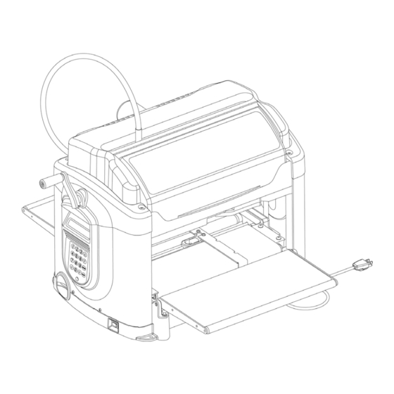
Hardware Features The key features of the CarveWright multi-purpose tool and their locations are shown in the following illustrations. Flexshaft Top Safety Assembly Cover Cutting Trucks Head Head Locking Head Crank Lever (Shown in Handle Non-Locked Position) Sliding Guide Plate LCD Display Release Lever Vertical Corner Post... - Page 16 HARDWARE FEATURES (cont.) Flexshaft Air Intake Cutting Motor Squaring Plate Muffler and Dust Collector Bag Sliding Guide Plate Folding Outfeed Outfeed Table Table (rear) Height Adjustment 11: F IGURE EATURES Top Compression Rollers 12: F IGURE EATURES ELOW UTFEED ABLE NOT SHOWN FOR CLARITY Board Edge Sensor LHR Technologies, Inc.
- Page 17 HARDWARE FEATURES (cont.) Vertical Moving Truck (Z-Truck) Y-Truck Guide Rails Horizontal Moving Truck (Y-Truck) Z-Truck Guide Rails 13: C IGURE UTTING SSEMBLY Overhead View of Machine (with workpiece) Z-Axis is up/down Right Workpiece Left Far-side Y-Axis Also referred to as the Front of the machine.
-
Page 18: Operation
Operation Using the CarveWright System Before the CarveWright can begin to function, the CarveWright memory card must be installed. With the power off, push the memory card gently into the memory card slot until it stops, making sure the label is up. WARNING: Never remove the memory card from the machine while it is on. -
Page 19: Navigating The Menus Via The Keypad And Lcd
Navigating the Menus Via the Keypad and LCD For input and display of information the CarveWright machine employs a tactile keypad and LCD display. All operations require the user to input information at the actual machine location via the keypad (as opposed to information input and passed through the CarveWright design software). -
Page 20: Keypad Data Entry
Keypad Data Entry When a menu option asks for numerical data, such as length or depth dimensions, the keypad is used to enter the data. When fractional values are involved, data may be entered as either decimals or fractions. Decimals are the simplest. To enter a decimal simply type the whole number then the decimal point (down-arrow key) followed by the decimal part (i.e. -
Page 21: Rip Or Cross Cut
WARNING: From the standpoint of safety, machine longevity, and output quality, it is important to follow all instructions concerning the proper bit to be used for each built-in function. For approved router bits, visit the CarveWright website. Rip or Cross Cut This function is provided to allow a board to be sized by width and/or length. -
Page 22: Bevel And Miter Cuts
If there is a significant crown to the board, place the highest point of the crown under the cutting head. This will allow the machine to measure the highest point of the crown and will prevent the machine from taking and excessive cut. Use the Repeat shortcut key as many times as necessary to eliminate the crown. -
Page 23: Measuring A Board
Measuring a Board The Measure Board function allows the user to measure the width or length of an existing board. Simply load a board in the typical way and press the ‘7’ (Measure) key on the keypad or use the up/down arrows to navigate from the main menu. -
Page 24: Carving A Project
Carving a Project A project is a set of related design elements (patterns or figures) created with the CarveWright design software and stored on the memory card. These stored projects are accessed from the keypad. Simply press the ‘1’ (Projects) shortcut key to open the Projects Menu which can then be browsed using the up and down arrows. - Page 25 Wood The machine can carve the full range of wood types from soft pine to exotic hardwoods. While every conceivable hardwood has not been tested, we have yet to find one that cannot be used in the machine. Carving hard materials with tight grains produce the best finishes. In most cases, feathering and chip out will increase as the grain size increases.
-
Page 26: Inserting A Board
Inserting a Board Proper installation of the workpiece is critical to the performance and continued operation of the machine. To properly insert a workpiece: 1. Press down on the sliding guide plate release lever and move the sliding guide plate to the right so that it will clear the width of the workpiece. - Page 27 Sliding Guide Plate Traction Drive Sliding Guide Plate Squaring Plate Release Lever Board Tracking Sensor Board Sensor Detail Release Lever Detail 19: W IGURE ORKPIECE NSERTION ETAILS 5. Gently push the sliding plate up against the inside edge of the workpiece.
- Page 28 The clutch is intended to load the board against the traction drive with consistent force. In certain cases the machine can sense if the workpiece is not loaded enough and repeatably display Please Load Board on the LCD. Most often this decreased loading is caused by insufficient lubrication of the four vertical corner posts or the two vertical leadscrews.
-
Page 29: Workpiece Preparation
Workpiece Preparation Before carving can begin a number of menu prompts and machine operations must be navigated. First, the machine will ask if the workpiece is to Stay Under Rollers. If YES to Stay Under Rollers is selected the machine will automatically assure that there is 3-1/2"... - Page 30 Scale the project to fit the workpiece or Load New Board. If the Scale option is selected then options Center On Board, Jog To Position, or Place On Corner are displayed in order to locate the project on the workpiece. WARNING: Be very careful when scaling down a project at the machine.
-
Page 31: Jogging The Cutting Truck
time estimate for the entire project can be obtained in the design software when the project is uploaded to the memory card. When the carving is completed, lift the top safety cover, release the head lockdown lever, and crank the head up to free the workpiece. The workpiece can then be removed and examined. -
Page 32: Workpiece Size Limitations
2. Cuts through the board along the top edge of the workpiece (as viewed in the software) can interfere with the Board Tracking Sensor and affect the machine's ability to track the position of the workpiece. 3. Carvings on the rear face of the workpiece and near the bottom of the workpiece (as viewed in the software) can also interfere with the Board Tracking Sensor when the workpiece is flipped over. -
Page 33: Quick Release Chuck
Quick Release Chuck The CarveWright™ System, with its computer-controlled 3-D carving and general woodworking capabilities, is a revolutionary breakthrough in bench-top power tool design. Central to the performance and versatility of the CarveWright machine is the patented Quick Release Chuck (or Quick Change). The CarveWright utilizes this quick release chuck system to make changing any-and-all CarveWright approved bits fast and easy. -
Page 34: Chuck Operation
Chuck Operation The quick release chuck operates very similar to the quick release fitting on an air hose. The three important parts of the mechanism are the chuck tapered body, the chuck spring loaded cap, and the tapered bit adapter (into which the bit is mounted). -
Page 35: Cocking The Quick Release Chuck
In the Cocked Position You Can See the Tapered Body 25: Q IGURE UICK ELEASE HUCK IN THE OCKED AND NON OCKED OSITIONS Cocking the Quick Release Chuck The quick release chuck must be cocked in order to install a bit. To cock the chuck, place a thumb in the z-truck grip ridge and pull up on the chuck release flange with the middle and index fingers of the same hand. -
Page 36: Bit Assembly Installation
In the event that the above methods do not result in a cocked chuck, please refer to the Chuck Troubleshooting section of this document for possible resolutions. Bit Assembly Installation Once a carving function has been selected from the display menu, the CarveWright machine will move the cutting head to the center of the machine and prompt for the user to insert the required bit. -
Page 37: Chuck Care And Maintenance
WARNING: Use caution to avoid being cut by the sharp cutting edges of the router bit. Use caution if the bit has recently been in use; it may be HOT and a glove will be required to handle it. Bit Release Tool Alternately, the supplied bit removal tool can be used to extract the router bit as... - Page 38 and bit. To check, simply insert a finger into the tapered body of the chuck from below with no bit present and move the finger back and forth checking for looseness. If looseness is detected in the spindle please contact CarveWright support to diagnose the problem. •...
-
Page 39: Chuck Troubleshooting
rust does appear on any of the quick release parts or bit adapters it must be removed and the parts re-lubricated. Any part with rust that penetrates deeper than the surface will need to be replaced. Do not leave bit and adapter assembled in the quick release chuck when not in use. -
Page 40: Cutting Bits
• Rust on the tapered interface surfaces • Bent screws on the bit adapter • Dimples on the bit adapter body • Distorted bit adapter Cutting Bits The CarveWright comes equipped with two bits mounted in bit adapters. These are the 1/16” tip diameter carving bit and a 1/8” cut-off bit. Additional bits and bit adapters, made to the CarveWright specifications, are available through the CarveWright web site. - Page 41 shank. Remove the two setscrews from the adapter body and de-grease both the setscrews and threaded holes. This can be done using rubbing alcohol or a product such as WD40. Thoroughly dry the parts. Apply a drop of permanent thread cement on each setscrew to prevent them from loosening and start the treads.
-
Page 42: Proper Bit Installation Into The Bit Adapter
Proper Bit Installation Into the Bit Adapter 1/2" Adapter Style – Assemble the bit so that the face of the adapter is 1/8” from the bottom of the cutting surface. (Correct) (Incorrect) (Incorrect) 31: C A. T IGURE ORRECT SSEMBLY IS SHOWN IN XAMPLE OW IN XAMPLE... -
Page 43: Carvewright Approved And Branded Bits
CarveWright Approved and Branded Bits Bit Name Shank LHR P/N 1/8” Straight Cutting 1/4" BCT125 WARNING: NEVER CUT DEEPER THAN THE 1/16” Tapered Carving 1/4" BCR062 LENGTH OF THE SHARPENED CUTTING SURFACE OF 1/16” Straight Cutting 1/4" BCT062-3F YOUR BIT. The maximum cut depth as stated in this Manual V-Groove 1/4"... -
Page 44: Care And Maintenance
Care and Maintenance The CarveWright is a precision machine tool. With proper care and maintenance it will provide long, reliable service. WARNING: Always unplug machine before attempting any troubleshooting or maintenance on the machine. • Initial Set-Up and Alignment - Adjusting the Head Pressure Checking the head pressure and adjusting the vertical guide rods is part of the machine set-up process. - Page 45 Flexshaft Support Tube End Of Flexshaft Support Tube Ball Detent Flexshaft Receptacle Z-Truck 34: V IGURE IEW OF THE LEXSHAFT ONNECTION TO THE RUCK 3. Remove the bottom cover. Carefully lay the machine on its back with the dust collection port facing down. Remove the 12 screws securing the black sheet metal cover onto the base (four of which are located in the rubber feet) and remove it.
- Page 46 head up and down as the crank handle is turned. Grab the tierod and verify that there is side to side play in the rod. The amount of play will vary between machines, but the important thing to note is that there is some side to side play.
- Page 47 7. Loosen one set of bottom screws securing the vertical guide rods. Slide one end of the machine 4 inches off the edge of the bench. It does not matter if it is the side with the keypad or the side without.
- Page 48 • Dust Removal: The CarveWright is designed to tolerate a considerable amount of carving system dust, but to ensure proper operation it should be kept free of debris as much as possible. Periodically blow or vacuum out any dust or debris from the recesses of the unit.
- Page 49 and let sit for an hour. After applying the specified lubricant slide the core back into its sheath. When near full insertion, the core may need to be carefully rotated with the fingers to ensure that its square end engages correctly with the cutting motor. Once the core is fully inserted in the sheath, it can once again be snapped into the cutting head.
-
Page 50: General Tips And Helpful Reminders
• General Tips and Helpful Reminders MAXIMUM CUT DEPTH for any operation is 1.0 inch or the full flute length whichever is shorter. PLEASE verify flute length of each bit before using. ALL MOTORS ARE DISABLED when the front safety cover is open. The cover must be closed before the machine can proceed. - Page 51 squaring plate is clean, smooth, and even for a width of at least 3/8 inch along the full length of the workpiece. o Keep all vector cuts at lease 3/4" away from the left edge. This will assure that the Board Tracking Sensor will remain in contact with the board at all times.
- Page 52 TO LOCATE FIRMWARE VERSION, use the Options shortcut key on the keypad to access the information. WHEN USING EXTERNAL DUST COLLECTION, make sure that the equipment is grounded according to the manufactured specifications. Electronics failure can occur if these procedures are not followed. WARNING: CUT ONLY WOOD, PLASTIC, OR WOOD-LIKE MATERIALS.
-
Page 53: Troubleshooting
Troubleshooting WARNING: Always unplug machine before attempting any troubleshooting or maintenance on the machine. • Checking the Board Sensor: There are several reasons why the machine will prompt the user to “Check the Board Sensor”. o There is dust obscuring the sensor. Please see the next section titled “Cleaning of the Board Sensor”... - Page 54 • Troubleshooting the Board Sensor If the board sensor error cannot be resolved by cleaning the sensor as outlined above, continue with the following troubleshooting steps. To check the status of the board edge sensor, go to the CarveWright Main Menu-Configuration-Sensor Check menu.
- Page 55 • Checking and Cleaning a Stuck Compression Roller - The top compression rollers are located on the underside of the head portion of the machine and assure that the workpiece is firmly pressed down onto the sandpaper belts during operation. These rollers are spring loaded in the up and-down-direction so that they can accommodate a small deviation in thickness as the workpiece moves in and out of the machine.
- Page 56 Checking the Compression Roller Sensors - Checking the compression roller sensors is very easy. Turn the machine ON and navigate to the Configurations Menu from the CarveWright Main Menu by using the up/down arrows or pressing the “0” (Options) key on the keypad. Navigate to, or select key “7”, Sensor Check.
- Page 57 • Calibrating Machine Offsets: The "Calibrate Offsets" function is a simple procedure to allow the user to fine-tune the CarveWright machine for improved accuracy. To perform the offset calibration, the following will be needed: - A board at least 2" wide by 10" long between 1/2" and 3/4" thick. - The CarveWright branded 3/8"...
- Page 58 Head Top Compression Rollers 42: H IGURE HOWING OMPRESSION OLLERS Checking the head pressure is very easy using a standard bathroom scale. 1. Before starting, make sure that the sliding plate is moved all the way to the far side of the machine and is out of the way of the scale.
- Page 59 • Please Check Board Errors: This prompt is shown when the board- tracking sensor is having difficulty monitoring the position of the workpiece accurately. This sensor tracks the position of the workpiece as it travels in and out of the machine. A small brass wheel rides along the bottom side of the material and provides position information to the control system.
-
Page 60: Checking The Machine's Onboard Sensors
Checking the Machine’s Onboard Sensors The status of each of the machine’s onboard sensors can be accessed from the LCD screen and keypad for the purpose of troubleshooting. To access the Sensor Check menu simply select the “0” (Options) key at the CarveWright Main Menu or use the up/down arrows to locate the Configurations Menu and then press ENTER. - Page 61 Z Position State – Numerical Value (0.000) The Z position sensor monitors the relative position of the up-and-down motion of the cutting truck. To check this sensor move the cutting truck all the way to the top of its vertical travel and record the displayed numerical value.
- Page 62 Congratulations on the purchase of your Remember These Great Resources for More Information… • The CarveWright Website (www.carvewright.com) (User’s Forum, Customer Gallery, Tutorials & so much more) • Software Tutorials (Step-by-step instructions on how to use the basic software functions) •...
Need help?
Do you have a question about the CW.01.01 and is the answer not in the manual?
Questions and answers
comment puis-je obtenir une carte mémoire pour le modèle CW.01.01