Advertisement
Quick Links
Advertisement

Related Manuals for Locinox FREE VINCI LFKQ X2L


Summary of Contents for Locinox FREE VINCI LFKQ X2L
- Page 1 FREE VINCI LFKQ X2L USER GUIDE ENGLISH...
- Page 3 Copyright © 2014 Locinox. All rights reserved. This product incorporates copyright protected technology that is protected by a number of EU patent method claims and other intellectual property rights owned by the Locinox Corporation and other rightholders. Use of this copyright protected technology must be authorized by the Locinox Corporation.
- Page 4 Manual - English 1. Introduction Thank you for choosing a Locinox mechanical code lock with free exit! Please read the following instructions thoroughly before mounting the Free Vinci. Enclosed you will find all relevant user information concerning the Free Vinci. 2. Package contents Please check if your package contains the following items: Please contact your supplier should any of the above items be damaged or missing. Mechanical code lock with free exit for swing gates 3006C/2 (Aluminium half club) & 3006R/2 (Aluminium half knob) Code screws, green (2x) Cover caps (2x) Allen key (3mm) (1x)
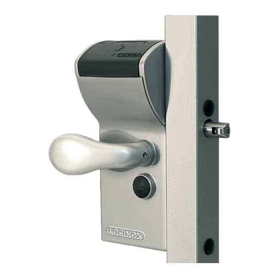
- Page 5 3. Components The drawing below shows the names of the most important components. This drawing can be used as reference throughout the manual. Rain and dust cover Code panel Reset button Half handle 3006C/2 Half handle 3006R/2 Self-latching bolt (D) Spacer tube Hex head socket screw Closing cover Cover screw 4. Specifications • The Free Vinci is a 100% mechanical code lock, which does not need a battery nor electricity to function. • The code lock is equipped with a single-side operational code panel. This enables you to work with an entrance code and a quick free-exit handle.
- Page 6 5. Profile preparation Determine the correct position of the lock in the gate frame. The mounting holes can be prepared by means of the drawing below. NOTE! The hole of the self-latching bolt, needs to be larger (Ø 1”) at the back of the gate frame then at the front (Ø3/4” mm). This allows you to fit the Free Vinci easily into the gate frame when a minimum distance (4-3/8”) between the gate frame and the first gate bar is required. 6. Changing the codepanel to the entrance side Before mounting the Free Vinci to the gate, check if the code entry side is at the correct side of the gate. If not, follow the instructions below to change the codepanel to the entrance side of the gate. Step 1: Remove the closing cover. First remove the cover screw and then slide out the closing cover and the dust- & raincover.
- Page 7 Step 2: Switch the code mechanism to the other side Slide out the code panel. Loosen the code mechanism screw and flip the code mechanism to the other side. Step 3: Remount the code panel Tighten the code mechanism screw. Change the personal code following the instructions in Chap- ter 7, Code setting. With the numeric plate in the correct position, you are ready to replace the code panel. CAUTION! The reset button always needs to be on the latch bolt side of the lock. Step 4: Reinstall the covers After inserting the code panel, insert the Dust and Rain Cover so the cover opens over the code panel. Slide the Closing Cover into position and tighten the screw. CAUTION! We recommend you test the lock function (see chapter 10 Operation) before mounting the lock.
- Page 8 7. Code setting Because of security reasons, the Free Vinci is developed in such a manner that the code can only be changed when it is not mounted. The default setting of the code is 1-2-3-4. The steps below explain how you can modify your own personal code in a fast and simple manner. The Free Vinci enables the setting of a 4 to 6-digit code. Step 1: Remove the closing cover and code panel. After removing the code panel, you will find the red (stop) and green (go) code screws. From the factory, the green screws are automatically set in position 1-2-3-4, as shown. Remove all code screws from the code mechanism with the enclosed Allen key.
- Page 9 8. Mounting the handles NOTE! The handle at the top position is the code entrance handle on the secure side of the gate. The bottom position is for the free exit handle on the “safe” side of the gate. CAUTION! Install the handle shaft so that the handle’s set screw tightens into the spreader side of the shaft. 9. Turn the rollerbolt to match the closing direction CAUTION! Before mounting the Free Vinci to the gate, check if the rollerbolt is in the correct position. If not, remove the screws and turn the rollerbolt. NOTE! We recommend Loctite BLUE threadlocker for the rollerbolt mounting screws. Tighten the screws securly. 180°...
- Page 10 10. Operation Enter a false code in order to test the reset function. Drawing A After having entered an incorrect code, the handle remains blocked. Drawing B Now press the reset button and enter the correct code. Drawing C & D. The handle can be moved after entering the correct code. This will retract the lock’s self-latching bolt. Drawing E. After using the handle, the code is automatically reset. In doing so, the code needs to be entered each time in order to open the Free Vinci. 11. Mounting the Vinci After testing the operation of your lock, the Free Vinci can be mounted onto the gate. The fast, easy and typical Locinox mounting is explained below. First slide the spacer tubes over the hex head socket screws and mount the lock onto the gate profile by using the hex key. & . Tighten the hex head socket screws and cover the holes with the enclosed plastic cover caps.
Need help?
Do you have a question about the FREE VINCI LFKQ X2L and is the answer not in the manual?
Questions and answers