Table of Contents
Advertisement
Quick Links
Advertisement
Table of Contents

Related Manuals for Ericsson AEGIS EDACS M-PA


Summary of Contents for Ericsson AEGIS EDACS M-PA
- Page 1 LBI-38794C Operator’s Manual AEGIS EDACS ® M-PA SCAN MODEL PORTABLE RADIO...
-
Page 2: Table Of Contents
ACCESSORIES ... . . 33 information, or improvements to programs and/or equipment, may be made by Ericsson Inc., at any time and without notice. Such changes will be incorportated into new editions GLOSSARY . - Page 3 PRODUCT SPECIFICATION FOR CE MARKED EQUIPMENT The M-PA Portable conforms to the following Product Specifications. EUROPEAN STANDARDS: Safety: Not Applicable EMC: prETS 300 279 (August 1995) TTD: Not Applicable SUPPLEMENTARY INFORMATION: At this time, the M-PA portable radio may not be operated while in a vehicular charger in the European Community since it has not been evaluated for opera- tion in this mode.
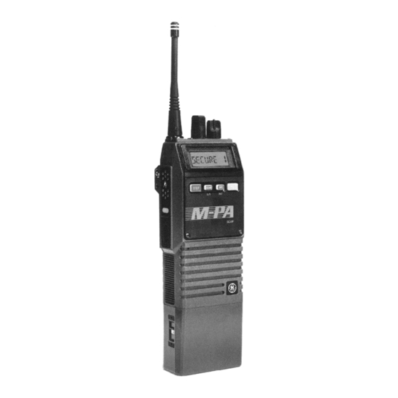
- Page 4 SIDE VIEW FRONT VIEW Figure 1 - Aegis EDACS M-PA Scan Model Radio...
-
Page 5: Introduction
INTRODUCTION transmitter on, scanning, or emergency mode en- abled. The Aegis EDACS M-PA Scan model portable The exact operation of your radio will vary de- radio is a high-performance two-way radio that pro- pending upon the mode of operation, the radio’s vides clear voice, Aegis digital, and Aegis private programming, and the particular radio system. - Page 6 VOLUME CONTROL KNOB status flag in the display will turn on when the radio is transmitting. Releasing the PTT BUTTON will return The VOLUME CONTROL KNOB is a rotatable operation to receive mode. control on the top of the radio used to adjust the receiver’s audio level in the speaker.
- Page 7 Conventional Mode When the radio is operating in conventional mode, the MONITOR BUTTON is used to unsquelch the receiver. If programmed for the selected channel, it will also toggle Channel Guard (CG) and/or Type 99 (T99) signalling on and off. Figure 2 - Keypad Momentarily pressing the MONITOR BUTTON In conventional mode, initiating an emergency...
- Page 8 STEP is also used to scroll through the pro- 2nd FUNCTION BUTTON grammed special call table when the special call Two (2) of the buttons on the keypad are dual- mode is enabled. function buttons. Press and release the blue 2nd SCAN BUTTON function button to shift keypad selection to the A/D and PVT buttons.
-
Page 9: Indicators
Scan must be turned off before groups or chan- INDICATORS nels can be added to or deleted from the scan list. See SCAN BUTTON for details. The radio’s liquid crystal display (LCD) located on the front panel has eight (8) alphanumeric characters PRIVATE BUTTON (Shifted SPC Button) and sixteen (16) status flags. - Page 10 The sixteen (16) status flags located along the top CNV CoNVentional mode - On indicates the radio is operating in the conventional and bottom of the display indicate operating modes mode. and conditions as follows: SPC SPecial Call mode - On indicates the spe- cial call mode has been enabled (trunked EMG EMerGency mode - On indicates an mode).
-
Page 11: Universal Device Connector
• priority 1 - On indicates the selected con- 500 Hz Tone trunked failure tone - sounds – ventional channel is designated as the when a trunked failure has oc- priority-one scan channel. curred (call denied, failed con- firmation) priority 2 - On indicates the selected con- low battery - sounds when the –... -
Page 12: Operation
• OPERATION Systems are selected with the STEP button; groups and channels are selected with the POWER-UP CONTROL KNOB. After the battery pack and antenna have been installed, turn the radio on by sliding the ON/OFF • Systems are selected with the CONTROL SWITCH on the battery pack up. -
Page 13: Voice Modes
Group/Channel Selection lease 2nd and then press STEP. Holding down STEP will cause the radio to automatically scroll through the After the desired system is selected with the group/channel list. STEP button, rotate the CONTROL KNOB to the desired trunked group or conventional channel as Upon reaching an end of the group/channel list, indicated in the display. -
Page 14: Aegis Digital Mode
Clear mode transmissions can be easily monitored by receive clear and digital signals. In other words, with unauthorized persons. Groups and channels pro- a certain group or channel selected, the operator grammed for clear operation cannot transmit or re- cannot change from the digital transmit mode but the ceive Aegis digital or private messages. - Page 15 must be equipped with the optional encrypt/decrypt When operating on a group or channel pro- feature and the transmitting and receiving units must grammed for private mode, all transmissions will be have identical cryptographic keys. private transmissions and the radio will receive clear and private signals.
- Page 16 Connect the Keyloader cable to the UDC on Key Zero the radio. All cryptographic keys can be zeroed or "dumped" Press the PWR button on the Keyloader and when the radio is on by simultaneously pressing the wait for the Keyloader to display "MASTER STEP and 2nd buttons for at least one second.
-
Page 17: Trunked Mode Operation
operation and the correct cryptographic key must be Continue with standard transmission proce- loaded into the radio. dures. In conventional mode, if a channel is programmed for private operation and pri- Transmitting An Encrypted Message vate transmit mode has been disabled, the radio will sound an alert tone when the PTT Select the desired group or channel. - Page 18 Adjust the VOLUME CONTROL to an ap- Responding to an individual call prior to the proximate mid-range position. programmed call-back time-out will automat- ically direct the transmission to the originat- Select the desired system and group using ing unit. the STEP button and CONTROL KNOB. See the SYSTEM/GROUP/CHANNEL SE- The "MSG"...
-
Page 19: Sending A Message
Sending A Message NOTES If a group is not programmed for private Turn the radio on, set the receive audio level mode operation, "PVT DIS" will momentar- and select the desired system and group. ily show in the display if an attempt is made to enable private transmit mode. -
Page 20: Emergency Operation
Release the PTT BUTTON when the trans- radio begins operation on the selected group mission is complete. If the transmission ex- or the home group, depending upon pro- ceeds the programmed Carrier Control gramming. Timer limit, the radio will unkey and an alert Press the PTT BUTTON and speak into the tone will sound. -
Page 21: Wide Area System Scanning
Private mode Dynamic Regrouping operates as ically scan the control channels of up to six other follows: systems. If a new control channel is found, the radio will switch to the new system and sound an alert tone. • When the radio is regrouped, all regroups will Group selection may change upon switching to the initially operate in clear mode. -
Page 22: Special Calls
ating procedures for specific procedures on conven- When a group on the scan list receives a tional channel scanning. channel assignment, the radio unsquelches on the assigned channel and the group Adding Groups To And Deleting Groups From name is displayed. The Scan List The radio will continue scanning if a new Scan must be off to add groups to and delete... - Page 23 be programmed into the radio and selected for trans- Press SPC. The radio enters special call mission. mode as indicated by the "SPC" status flag. The last selected special call will be dis- Receiving An Individual Call played. Scroll through the special call table by pressing STEP or 2nd-STEP until the When an individual call (a call directed to only one desired special call name appears in the...
-
Page 24: Conventional Mode Operation
When the call is completed, the radio re- When the called party answers, press the mains in the special call menu for a pro- PTT BUTTON and speak into the micro- grammed amount of time. To return to group phone. Unlike a regular telephone, you may selection, press and release SPC or the not talk and listen at the same time. -
Page 25: Sending A Message
Using the CONTROL KNOB and STEP but- If the transmission being received is an en- ton, select a conventional channel. See the crypted transmission and the selected chan- SYSTEM/GROUP/CHANNEL SELECTION nel is programmed for private operation and operating procedures for details. The dis- the correct cryptographic key is loaded into play will indicate the selected channel’s the radio, then the receiver will unsquelch,... - Page 26 NOTES flag. If the Channel Busy Lockout feature is If a channel is not programmed for private mode programmed for the selected channel, the operation, "PVT DIS" will momentarily show in radio will not transmit when the channel is the display if an attempt is made to enable busy.
-
Page 27: Emergency Operation
Emergency Operation (Conventional Mode) The radio will not scan when the emergency mode is enabled ("EMG" status flag is on). To enable an emergency transmission, press the EMERGENCY BUTTON for approximately one (1) Adding Channels To And Deleting Channels second. If an emergency channel is programmed, the From The Scan List radio will switch to the emergency channel, turn on Scan must be off to add channels to or delete... -
Page 28: Operating Tips
• "SCAN DIS" The radio is not pro- non-priority channel is being received, the display – grammed to scan. name is updated, the applicable status indicator, "1" or "2" lights, and the channel is switched to the priority • "FIXED P1" A priority-one channel –... -
Page 29: Operating Rules And Regulations
direction or moving to a higher elevation may also When using your two-way radio, remember these improve communication. Vehicular operation can be rules: aided with the use of an externally mounted antenna. It is a violation of FCC rules to interrupt any Battery condition is another important factor in the distress or emergency message. -
Page 30: Battery Packs
Using your radio to send personal messages BATTERY PACKS (except in an emergency) is a violation of FCC rules. You may send only those mes- INSTALLING THE BATTERY PACK sages that are essential for the operation of Ensure the ON/OFF SWITCH on battery your business. -
Page 31: Charging The Battery Packs
Figure 5 - Removing the Battery Pack Figure 4 - Installing the Battery Pack Chargers are available with nominal charge times CHARGING THE BATTERY PACKS of 1 hour (rapid) and 14 hours (standard). Combina- After receiving a new rechargeable battery pack tions include single (1) and multi (5) position, standard from the factory, it should be fully charged before and rapid charge units. -
Page 32: Rechargeable Battery Pack Disposal
The rechargeable batteries used with the radio SWIVEL MOUNT REMOVAL AND can develop a reduced capacity condition sometimes REPLACEMENT called the "Memory Effect". This condition can occur when a battery is continuously charged for long peri- To remove the swivel mount, slide a flat blade ods or when a regularly performed duty cycle allows screwdriver underneath the spring retainer and twist. -
Page 33: Intrinsically Safe Usage
INTRINSICALLY SAFE USAGE PAPA1F Rechargeable Battery Pack, Extra High Capacity (Tall Case) Selected portable radios with appropriate factory PAPA1G Rechargeable Battery Pack, installed F4 Options are certified as Intrinsically Safe High Capacity (Short Case) by the Factory Mutual Research Corporation. Intrinsi- ACCESSORIES cally Safe approval includes Class l, II, Ill, Division 1 hazardous locations in the presence of Groups C, D,... - Page 34 PANC1F Antenna, 440-470MHz, Helical PANC1L Antenna,378-440MHz, Whip PANC1N Antenna,440-512MHz, Whip PANC1H Antenna, 806 - 870 MHz, Ele- vated Feed PANC1K Antenna, 806-870MHz, Flex PANC1U Antenna, 378-440MHz, Helical PANC1Z Antenna,896-941MHz, Whip PAHC1C Belt Clip PAHC1D Swivel Mount with Belt Loop PAHC3W Case, Leather, with Belt Loop (Short Case) PAHC1K...
-
Page 35: Glossary
GLOSSARY CCT - Carrier Controlled Timer - a pro- grammable timer that will disable clear mode - communicating in an analog for- a transmission if the timer length mat which is non-digitized and is exceeded non-encrypted CG - Channel Guard - a method of control channel - a radio channel in a trunked sys- controlling squelch with a tone or... - Page 36 private mode - communicating in an encrypted namically allocated to groups of format (scrambled) people for communication pur- poses queueing - the process that occurs when all channels in a trunked system are trunked system - a set of one or more trunked busy and calls must be ad- groups dressed on a priority basis...
- Page 37 SYSTEM SYSTEM TRK/ GRP/CHN GRP/CHN VOICE NUMBER NAME NUMBER NAME MODE* * C=Clear, D=Digital, P=Private, V=Voice Guard Private...
-
Page 38: Warranty
WARRANTY Ericsson Inc. (hereinafter "Seller") warrants to the original purchaser for use (hereinafter "Buyer") that Equipment manufactured by Seller shall be free from defects in material, workmanship and title, and shall conform to its published specifications. With respect to any Equipment not manufactured by Seller (except for integral parts of Seller’s Equipment to which the warranties set forth above shall apply). -
Page 39: Nickel-Cadmium Battery Warranty
NICKEL-CADMIUM BATTERY WARRANTY Ericsson Inc. (hereinafter "Seller") warrants to the original purchaser for use (hereinafter "Buyer") that nickel-cadmium batteries supplied by Seller shall be free from defects in material and workmanship, and shall conform to its published specifications for a period of twelve (12) months from the date of purchase. - Page 40 EMERGENCY NUMBERS Police State Police Fire Poison Control Ambulance Life Saving and Rescue Squad Ericsson Inc. Private Radio Systems Mountain View Road Lynchburg, Virginia 24502 1-800-592-7711 (Outside USA, 804-592-7711) Printed in U.S.A.