Table of Contents
Advertisement
Quick Links
Advertisement
Table of Contents

Related Manuals for ROBBE FX-20


Summary of Contents for ROBBE FX-20
- Page 1 Instruction manual FX-20 No. F8072...
-
Page 2: Table Of Contents
9.7 Stick mode selection .......... 2 2 11.8 Aileron -> Camber Flap mixer ......38 3.2 Receiver R6108 SB 2,4 GHz ........ 9 9.8 Switch - Switchtyp Assigment ......22 11.9 AILeron -> Brake Flap mixer ......... 3 9 9.9 Information ............23 11.10 AILeron -> Rudder mixer ........39 FX-20 transmitter controls ........ 9 11.11 Spoiler -> flap (Camber mix) ........ 39 4.1 Turning transmitter on and off ......10 Linkage menu (LNK) ........11.12 Elevator -> camber mixer ........40 4.2 LED monitor ............10 10.1 Servo ..............23 11.13 Camber flap -> Elevator mixer ......41 4.3 Stick adjustment ........... 10... -
Page 3: Set Delay Time
13.8 Gyro settings ............57 Always maintain correct polarity. This radio control system is designed and approved exclusi- 13.9 Governor settings ..........58 vely for use with radio-controlled models. If you use the equip- 13.10 Fuel mixture settings ..........59 Avoid subjecting this equipment to undue shock or pressure. ment for any other purpose, Robbe Modellsport will accept no Check your system regularly for damage to cases and wiring. liability for the consequences. Programming example for FX-20 Tx If a unit gets wet or is damaged in a crash, it should not be example 4 flapped glider wing......60 used again even after you have dried it out and checked it tho- SAFETY NOTES roughly. The only safe course of action is to replace damaged Radio-controlled models are not toys or playthings in the usual Tx software update ..........82 items, or at least have them checked by the robbe Service. meaning of the term, and young people should not operate... -
Page 4: Safety Precautions, Observe At All Times 1. Contents
Universal mode. They can be easily other public waterways. Receiver battery 4.8V 1400 mAh No. 4551 converted from „throttle left“ to „throttle right“ by the owner. Spare Tx battery LiPo 7.2V 3400 mAh No. 4846 • You must not operate your model from public roads, motor- ways, paths, squares etc. Wireless Trainer System No. F1414 • The FX-20 transmitter features the new rotary stick trim- Rx charge lead No. F1416 ming. This type of trimming combines the advantages of tra- Never operate your equipment in stormy weather. Transmitter case No. F9906 ditional analogue trims with those of digital trimming. With Ali. Case for tray Tx No. 8899 just one movement, the direction and size of trim required Don’t “point” the transmitter aerial straight at the aeroplane... -
Page 5: R-6108 Sb Receiver
General FX-20 R-6108 SB RECEIVER RECEIVER STATUS LED INDICATION (R6008HS) ICONVERTING FROM ANALOGUE TO DIGITAL SERVOS The factory setting is set to “Normal” mode and suits the com- Full range 8/18-channel 2.4 GHz FASST receiver, slimline and monly used Analogue servos. To achieve a quicker reaction on LED green LED red Status lightweight for models with narrow fuselage/hull. With a serial channels 1-6, which leads to a further improved reaction time bus (S-BUS) - system for up to 18 channels and so perfect for when using Digital Servos, use the following method. Setting Solid No signal reception large scale model aircraft. Outputs 1...8 can have 8 traditional of the digital mode: analogue or digital servos attached. The R 6108SB receiver has a switch to select between digital and analogue servos. Solid Receiving signals 1. Switch off the receiver after “binding”. 2. During the switching on of the Rx, press the Link/Mode but-... -
Page 6: Connecting The Servo Using Pwm
General FX-20 CONNECTING THE SERVOS USING PWM S-BUS CHANNEL ALLOCATION Channel In contrast to standard servos, where the receiver has a single Output Connecting the servos and power supply: PWM pulse per servo channel, S-BUS systems no longer have Mode A Mode B R6108 SB 2,4GHz receiver (Rx) classic individual servo channel alloocations. Outputs 1...7: 1 ... 8 Proportinal channels for Servos. Connection: B = Receiver battery / channel 8 Information relating to how far and in which direction the servo is to run is digitally coded, similar to the PCM system for trans- The switched putputs DG1+DG2 are accessible on the 8 chan- mitters. The pulse telegram additionally contains the direction nel R-6108 SB receiver only via the S-BUS outputs (channel and travel of all 18 servo channels as well as the channel 9+10). - Page 7 General FX-20 MIXED CONNECTION max. curent 6A / 12 A continuous Note: Hubcable 30 cm No. 88830030 The maximum S-BUS channel count is 16+2. However, only CONNECTION TO S-BUS OUTPUT the same number of channels as the transmitter posesses are Up to 18 (16 prop channels, 2 switching channels) of the new, available for use (currently 8+2 or 12+2). programmable S-BUS servos can be connected in parallel di- rectly to this output. Using digital addressing, the servo will only Important: A battery connected directly to the receiver can make available react to information which has the correct servo address current at 3 A permanently and 6 A short-term. To use the S-BUS output, connect corresponding S-BUS ser- Hubcable No. F1697 max. current 6 A / 12 A continuos vos via the S-BUS HUB No. F1697 or No. F1698 or V-lead No. F1423 to the S-BUS connection at the receiver. Note: Individual S-BUS servos can also be connected di- HUB-4 with power current conection No. 8884 rectly. Accessories: max. curent 3A / 6 A continuous A second battery connection should be made on to the connec- tor strip of the receiver for higher power requirements. The cur-...
-
Page 8: Receiver Output Configuration For Aircraft
General FX-20 2.5 RECEIVER OUTPUT CONFIGURATION FOR AIRCRAFT Key: control terminology 1 Ail: 1 aileron Model type Power model 2 Ail: 2 ailerons Rx output 1 aileron 2 aileron 2 ail+1flap 2 ail+2flap 2 Ail+1flap : 2 ailerons + 1 camber flap 2 Ail+2flap 2 ailerons + 2 caqmber flap Aileron Aileron Aileron Aileron 2 Ail+2flap+2brakes: 2 ailerons + 2 flaps + 2 airbrakes/spoilers Elevator... -
Page 9: Technical Data
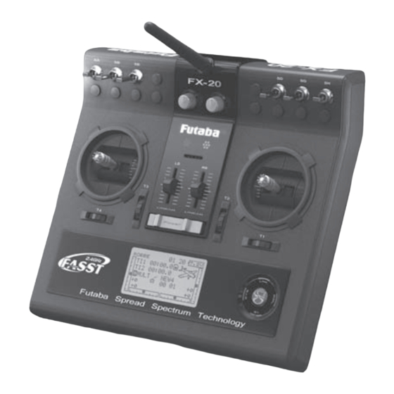
General FX-20 TECHNICAL DATA FX-20 TRANSMITTER CONTROLS FX-20 TRANSMITTER Control channels: ..........8+2 channels Frequency band: ...........2,4...2,4835 GHz Volume / rotary Antenna Alternative: ............2,4...2,454 GHz control “LD)” Carrier system: ..............FSK Volume / rotary Data resolution: ............2048 kHz Switch “SE” control “RD)” Power supply: ......7,2 V LiPo-battery / 3,4 Ah Power consumption with RF: ......approx. 220 mA Switch “SB” Switch “SD” Dimensions: ..........205 x 220 x 55 mm Weight (with battery): .........approx. 885 g Switch “SA” Switch “SG” Switch “SH” R-6108 SB 2,4 GHz RECEIVER Operating voltage: ....4,8 - 6 V (4-5 cells NC/NiMH) Current consumption: ..........ca. 50 mA LED monitor Number of channels: ............8/18 Data resolution: ............2048 kHz Linear slider “LS”... -
Page 10: Turning Transmitter On And Off
General FX-20 TURNING TRANSMITTER ON AND OFF STICK ADJUSTMENT LIQUID CRYSTAL DISPLAY (LCD) • Slide the main power switch on the Transmitter (Tx) to the The FX-20 Tx has new precision gimbal sticks, fitted with ball The large, clear-view and high contrast LCD graphics monitor right. bearings and long-life potentiometers to the latest industry (with 128 x 64 dots) supplies the user with all the necessary • The right hand red monitor indicates RF radiation after first standards. Emphasis has been placed on the best control “feel” information required for programming and operation. monitoring the local RF environment. around the neutral point of both stick axes. • The Display shows the symbol for RF radiation EXTENDING STICK LENGTH The stick length is fully adjustable and may be set to the opti- mum length to suit the pilot’s need. -
Page 11: Digital Trim Buttons
General FX-20 DIGITAL TRIM LEVERS ACTIVATION OF THE STICK RATCHET FUNCTION CHANGING THROTTLE FUNCTION (STICK MODE) The 4 digital trim controls for the sticks (T1…. T4) are rotary The Tx is delivered as Mode 2 as standard, left stick fitted with trims located near the sticks. You can freely assign these for Aircraft models will usually have a ratchet fitted to the throttle ratchet throttle and right stick with self-centring. Either stick use as trims, as other control inputs or as inputs for mixer func- stick to hold it in any set position. To do this, disconnect the may be chosen for use as a positionable throttle control. tions. self-centring of the throttle stick by tightening the cover plate Remove the control cover plate by loosening the marked screw screw on the relevant stick. This will disconnect the stick self- and transfer to the other stick unit, refit the screws. Each time, the trim value to the default Step change. Reached centring. Additionally, the throttle ratchet is already fitted to the neutral position of the trim-(Center) or the neutral run over, this plate, which gives an immediate ratchet function. To make... -
Page 12: Rotary Control Knobs
LINEAR SLIDER CONTROLS Both the slider controls can be used as trim controls or as con- trol inputs. They have a neutral detent and give an acoustic beep when reaching their mid-position. locking lug FORMATTING SD CARD Before you can write data to the SD card, it is necessary to format the memory first as follows: • Plug card into Tx and switch on power. The following mes- sage will appear: THIS CARD HAS NOT BEEN INITIALI- ZED. CANCEL / FORMAT • If the FX-20 is ready to format, move the cursor to [FOR- MAT] and touch the RTN button. This needs to be confir- med with OK, (To cancel formatting, move the cursor to [CANCEL] and touch the RTN button). • FORMATTING CARD will appear in the display and pro- gress indicated by a bar diagram. • Dependent on the size of the card, this process can take a few minutes. • Following successful formatting, FORMAT END will appear in the display. • The Tx will automatically return to Start Menu... -
Page 13: Removing Sd Card
Special software “Futaba File System Utility” to manage, (Save panels. and delete) the Data may be found in Download area of the MEMORY CAPACITY robbe Support Server http://www.robbe.com/rsc. Internally, the Tx has 20 model memories as standard. An opti- onal SD card can be used as a medium to expand the memory capacity, and the Tx can accept cards from 32 MB upto 2 GB. One SD card with 2GB can have 3862 model memories stored. The SD card may also be used as a medium for the user to upload any software updates from a PC to the Tx. The software for this is in the Download area of the robbe website home page. Update disscription see page 64 Note: Never remove battery when the monitor LED is flashing. This ADVICE FOR USING SD CARDS • Don’t remove the SD card during the memory back-up pro- could cause damage to the stored settings and the memory itself. If this occurs, don’t use the Tx and return to robbe service cess. department. • Keep strong magnetic and electrical fields away from the SD card. Data can be corrupted or lost. -
Page 14: Rc Charger, Charging The Trasmitter Battery
FX-20 RC CHARGER, CHARGING THE TRANSMITTER Caution: BATTERY The battery pack (No. 4846) has an integral Equalizer- and Pro- tection circuits, which protect the cells from overcharging. To save energy, the battery should be removed from the charger after 8 hours. The battery must only be charged using the RC charger supplied in the set! Chargers such as the Power Peak Infi- nity and similar are not suitable, as these devices are desi-... -
Page 15: Menus And Navigation
Navigation FX-20 MENU STRUCTURE AND NAVIGATION • The S1 key is to leaf through page 1/2 to page 2/2 of the • To lock the CAP TOUCH SENSOR from accidental use, selection menu levels. press the S1 key for 1 second when in the Start Display. The FX-20- navigation is logical and easy to use. The „CAP The key lock symbol will appear in the display as illustrated TOUCH SENSOR“, work as user controls. Example: Page Number below. The Menu-Structure is divided into three separate main menus, System (SYS)-, Linkage (LNK) - and Model (MDL). From the individual menus, one can choose from the different data sub menus. 1Sek. • To unlock, press the S1 key again for 1 second. • Holding the S1 key for longer than 1 second in a sub menu will return you to the Start Display. A few of the selection and data menus have sub menus with more than one • The CAP TOUCH SENSOR is fitted with 4 user functions. -
Page 16: Start Display Description
Display FX-20 HOME SCREEN/ START DISPLAY DESCRIPTION The most important information about transmitter programming is displayed in the Home/Start Display. These direct menus can be accessed direct from the Start Display. Scroll the „CAP TOUCH SENSOR“ to highlight the required menu and touch the “RTN“ key (see page 16) to select the relevant data entry menu. START-DISPLAY FOR ALL MODEL TYPES Timer 1 Username Start / Stop Timer System-Timer SD card Voltmeter Display field of Highlight and press Shows operating time indicator Voltage drops below 6,8 V and Stopwatch 1. Mark „RTN“ for 1 second in hours, minutes and an alarm sounds. Operation must and confirm to to reset time. seconds. Mark and cease as soon as possible. enter the ST1 ad- press „RTN“ for 1 sec. -
Page 17: Control/Switch H/W Select Menu
Switch selection FX-20 CONTROL INPUT / SWITCH SELECTION MENU If a control stick or proportional control were selected, more LOGIC-FUNCTIONS functions can be adjusted in the following display. The FX-20 software contains a comprehensive control input selection menu. Virtually all functions can be allocated to any control input. It doesn’t matter whether they are for a switched To set the switch position, move the desired switch to the re- or proportional control or a flight condition. The appearance of quired position and move the cursor to SET and press “RTN” the selection menu is always the same. key. The switch point is now indicated on the displayed bar chart. As soon as a function is selected and confirmed with “RTN”, the following Hardware Selection (H/W SELECT) menu will ap- ON / OFF pear. Please note that this menu differs somewhat from func- This menu defines the switch direction sense, „NORM“ Normal Certain functions, such as flight condition can be also opera- tion to function, according to the application, the display and or „REV“ reverse direction. ted/switched with a logical cascade of two switches; this is the selection changes according to the selected application. The so-called Logic-Function. example shows the switch selection menu for the “program- mable mixer” function. All relevant controls, switches and trim... -
Page 18: Timer
Activating this („ON“) stores the last stop time when chan- ging model memories or turning off transmitter. When swit- Note: ching on again the stored time value will be used. This is The FX-20 Tx has an automatic Timer, which reminds the useful to record the total running time of a motor. user how long the Tx has been switched on. If, after 30 mi- nutes, there has been no control input operation of sticks, • Change the preset time switches etc., an alarm sounds. -
Page 19: System Menu (Sys)
Scroll the “CAP TOUCH SENSOR” to select the function and flying skills under the supervision of an experienced instructor. ner cord combinations: the following display will appear: Connect the two transmitters using the correct trainer cord, which is available separately as an accessory from FX-20 transmitter may be used as instructor transmitter your dealer. The FX-20 transmitter can be used as either as with the following student transmitters: the instructor or as the student transmitter. Instructor Student... -
Page 20: Trainer System
System Menu FX-20 TRAINER • SWITCH: respective transmitter. Select the Trainer switch to be used to transfer control to/from Highlight and select the „TRAINER option in System menu and the student transmitter. Mark and confirm this option. The next This mode will hand over the relevant functions to the student confirm with “RTN”. sub-menu can be used to define switch operation direction. transmitter. Thereby, the student transmitter uses all the mixer settings of the student transmitter which are nee- On the 4 pages (1/4-4/4) of the „TRAINER” menu, all basic •... -
Page 21: Trainer As Student Tx
System Menu FX-20 TRAINER OPERATION AS STUDENT TRANSMITTER DISPLAY SETTINGS To configure the transmitter for use as a student transmitter, The adjustment menu “DISPLAY” is used to adjust contrast, the Trainer system must be turned off and the individual func- brightness and the display illumination time. tions set to “OFF”. DISPLAY CONTRAST ADJUSTMENT Entering the number of channels is important and is depen- dent on which instructor transmitter is being used. The correct channel setting, (7CH/MULTI) needs to be selected according Activate the “CONTRAST” item and change the contrast set- to which instructor transmitter is used. ting by scrolling the „CAP TOUCH SENSOR“. Scrolling left re- duces the contrast, and to the right increases contrast. OPERATION WITH A FLIGHT SIMULATOR To reset the contrast to factory setting, select and mark the item and press the ‘RTN’-key for 1 second and the original To be able to operate the T8 FG transmitter with a flight simu- setting will be displayed (5) again. -
Page 22: User Name
System Menu FX-20 USER NAME of the line and displays the original name. CHANGING STICK MODE This allows you to enter your own name. This will always ap- ENTER: After changing the throttle stick ratchet in 4.6, the software pear in the Start Display. The „ENTER“-command serves to confirm and accept the must be updated with the new selected stick mode. The soft- entered data. ware supports three further stick modes in addition to the fac- tory default, mode 2. Therefore, you may set the system to suit your chosen familiar stick mode. The servo outputs on the Rx The „ARROW“- command serves to control the cursor in the remain the same, but to ensure all other functions work cor- user name. rectly, the stick mode is changed as follows: DELETE: 1. Select [STICK MODE] in System Menu and access the... -
Page 23: Information
Linkage Menu FX-20 INFORMATION LINKAGE-MENU This menu has information about the product serial number, The Linkage Menu is made up of functions, which perform Idle Down: Lowers the idle speed of the engine language, software version, geographical area and model me- model addition, model type selection, frequency setting, end Trim-Adj: Trim step adjustment + Trim memory mory. point setting, and other model basic settings. Their data will be Mix Alarm: Warning of any mixers stored within a model memory in a separate memory. Data Reset: Reset data to factory default The linkage menu is described in detail below: Note: Dependent upon the chosen model type, there are some small differences in the individual displays in the airplane, glider and helicopter linkage menus. 10.1 SERVO Serial number: The transmitter serial number The „SERVO“ menu shows the servo throw, which have been... -
Page 24: Model Select
Linkage Menu FX-20 Servo test operation 10.2 MODEL SELECT • Thereafter, the new model memory may be used. As well as selecting the model memory data, this menu will Neutral Position “Neutral” CREATE NEW MODEL MEMORY also be used for the entire handling of model data, such as The transmitter will centre all channels. This is ideal to check • Highlight „NEW“ and activate. For safety reasons, the RF creating, copying, deleting and renaming model memories. that servos and arms are in their neutral position when adju- transmission will be stopped. The model must be shut off. sting linkages. • Confirm the following safety question by pressing the r A model memory occupies approximately 500 kB, and up to ‘RTN’-key for 1 second. 20 Models can be stored internally, and on a 32 MB SD card- Scroll the „CAP TOUCH SENSOR“ in Test mode from the... -
Page 25: Rename Model Memory
Linkage Menu FX-20 MODEL MEMORY RENAME 2) Thereafter, the memory place and the target file must be 10.3 MODEL TYPE • If requiring to rename a model, select from the list in the selected and confirmed with the ‘RTN’-Key. memory medium (TX/CARD) and confirm with “RTN”. - TX or In this menu, the wing and tail types will be selected. With heli • Highlight ‘RENAME’ and confirm with “RTN”. A new display - CARD. models, the swashplate mixing appropriate to the model type appears with all available alphanumeric characters. selection will be displayed. 3) Finally, the ‘COPY’-command must be highlighted with the S1= binder cursor and confirmed by pressing ‘RTN’-key for 1 second. This reduces the display to an absolute minimum and helps as Rotating the “Cap Touch Sensors” interrupts the process. an overview. Additionally, using “ADD-LIST” can overwrite an existing model memory. Note: The model- and wing type selection must be made before the When copying and overwriting, an automatic indexing num- model adjustment menu, because a change of the model and ber -1, -2 etc. will be allocated to the model name. If the... -
Page 26: Select Wing And Tail Type
Linkage Menu FX-20 The following model type selections are available. Display selection and confirmation message. There are a total of four swash types that may be used: • Model Type: Airplane - Helicopter - Glider • Wing Type: (Normal: 1 Aileron, 2 Aileron, 2 Aileron- •H-1: 1 Servo control 1 Flap, 2 Aileron - 2 Flap. Gliders also have: 2 Aileron- 2 Flap- 2 Spoiler, 4 Aile- •H-4: 2 Elevator and 2 Aileron Servos ron- 2 Flaps. Flying wing: 2 Aileron, 2 Aileron- 1 Flap, 2 Aileron-2 Flap • HR3(120): 3 Servos spaced at 120° (1 Elevator-, Aileron 2 Aileron-2 Flap- 2 Spoiler, 4 Aileron- 2 Flap and Elevator servo). • Tail or Rudder Type: (Normal, V-Tail and Ailvator (2. Ele- vator) for Airplane and Glider models. Switching to flying • H-3(140):... -
Page 27: Frequency Modulation Mode Fasst
Linkage Menu FX-20 10.4 FASST FREQUENCY MODE SELECTION-7 CHANNEL 10.5 CHANGING FASST AREA FREQUENCY BAND Recommendation: For countries such as Austria, France, Russia, Italy and Bel- / MULTI Select “FREQUENCY” in Linkage Menu and access set up gium, select the frequency range 2 (2400...2454 MHz) “France” The transmitter can be operated in 2 different modulation screen. Romania and Bulgaria require an additional general permission... -
Page 28: Function
Linkage Menu FX-20 10.6 FUNCTION SELECTION/ASSIGNMENT OF TRIM CONTROLS The trim buttons are freely selectable. The method is identical When you choose the model and wing types, you will find that to control input assignment. Highlight and confirm the ‘Trim’ optimized combinations of servo channels and control inputs/ field of the required function, the trim set up screen is displa- functions have been factory preset for the model type selection. yed. We recommend that you keep these, wherever possible, so In this menu the symbols may be selected and allocated on the that a common allocation of controls to their respective servo functions is maintained. left hand side of the display. The “FUNCTION” menu will display an overview of which re- TRIM SETTINGS ceiver outputs, their respective servos and which transmitter This menu allows further adjustments to be made: control input operates them. Functions with 2 or more servos are already configured with the appropriate transmitter con- trol input mixing. The configuration varies only slightly within a model type and, the number of allocated channels will be dependent upon the number of controls and flaps. This differs when changing model type. If the model type is... -
Page 29: Sub Trim Servo Centring
Linkage Menu FX-20 Throttle Trim Lock (only Gliders and Helicopters) FUNCTION CHANGE 10.7 SERVO CENTRE ADJUST/ SUB-TRIM To be able to assign the functions to the correct channel, the When installing servos in a model, it is always best to ensure So that the throttle trim does not get accidentally moved the function can be moved or assigned to another servo output that the servo arm is in the neutral position when the transmit- throttle trim levermay be locked so that it is inactive in all flight channel. ter control and trim are also in the neutral position. If it is not conditions except „NORMAL“. possible to achieve this or you find that the neutrals are incor- To achieve this, select and highlight the function required. Then rect on a model where the servos are already installed, the To be able to lock the throttle trim in Glider and Helicopter the new function can be selected from the menu. -
Page 30: Servo Reverse
Linkage Menu FX-20 The previous made setting can be reset Highlight ‘FAIL SAFE’-Option with the „CAP TOUCH SENSOR“ to factory setting (0 steps), when “RTN” is in linkage menu and confirm choice with “RTN”. presses for at least 1 second. 10.9 FAIL-SAFE SETTINGS 10.8 SERVO REVERSE In 7 CH operation, the Failsafe Function is limited to chan- This menu has a sub-menu for channels 5 to 8, the page This function electronically reverses all servo directions. This nel 3 (throttle) and cannot be changed. In „MULTI“ operation, number shows these. Highlight the “F/S” item of the chan- nel to be set with the “CAP TOUCH SENSOR“. Scrolling the... -
Page 31: Servo End Point/Travel Adjust
Linkage Menu FX-20 set up display. In the sample screen shown, switch SA is being 10.10 SERVO THROW ADJUSTMENT (END POINT) Limit-Point Adjustment The setting of the limit points follows the same procedure. used as the release switch. This function allows the servo Highlight the required field and adjust using the “CAP TOUCH throws for all 8 channels to be set SENSOR“. The limit point may be set for each servo travel each side of the neutral position. -
Page 32: Idle Down Preset Throttle Position
Linkage Menu FX-20 Highlight the throttle cut position (POS) and set the servo po- 10.12 IDLE DOWN 10.13 DIGITAL TRIM SETTINGS (T1-T4 SET) sition by scrolling the “CAP TOUCH SENSOR“ to the desired %-age value of servo travel. The adjustment range lies bet- The “IDLE DOWN” function allows you to reduce the motor Select (T1-T4 SET) in the Linkage Menu using the “CAP ween 0 and 50%, the default value is 17%. Pressing the ‘RTN’- r.p.m. quickly to a reliable idle position by operating a switch TOUCH SENSOR“ and access the set-up screen below by key for at least 1 second will return to the default setting. -
Page 33: Warning
Linkage Menu FX-20 10.14 WARNING 10.15 DATA-RESET One can programm an alarm to warn of unwanted mixers as When setting up a new model memory, this allows you to reset well as incorrect flight conditions being active during the trans- all the stored data to factory pre-set values. mitter switch on sequence. • Reset trim settings (T1-T4 active Flight Condition) This function serves as safety device for the operator and the This sub-menu resets all trim settings saved in the active model, by preventing inadvertent settings on the transmitter, flight condition back to factory pre-set such as incorrect stick position being used during motor star- ting. Then select the appropriate control trim display scale and press • All Model Data Reset “RTN“ key for at least 1 second. The setting is confirmed when This sub-menu resets all Linkage- and Model- menus a beep is heard and the trim display re-sets to 0%. -
Page 34: Model (Mdl) Menu (Airplane)
Model menu FX-20 MODEL-MENU (AIRPLANE AND GLIDER MODELS) • AILVATOR: Ailvator settings 11.1 SERVO, SEE PAGE 22 11.2 FLIGHT CONDITION (GLIDER ONLY) • WINGLET: Winglet-function These functions of the model menus, which will be described • MOTOR: Motor settings individually in more detail, act as the additional adjustments • RUD->ELE: Rudder -> Elevator Mixer The T8FG Software has five different flight conditions or phase that can be carried out on a model type as well as model me- • SNAP ROLL: Snap-Roll-Function settings available per model memory. For the different phases mories. -
Page 35: Copy Flight Condition
Model menu FX-20 • EX-OR: Either -Or selective coupling or exclusion of defined • PRIORITY CHANGE The throws are set separately for the right and left of servo switches. E.g. EITHER “SA OR SB“ activates the Highlight the flight condition that you wish to change priority neutral position. To do this, highlight the throw to be set with function. using the “CAP TOUCH SENSOR“. Using the “CAP TOUCH the ‘CAP TOUCH SENSOR. SENSOR”, the highlighted flight condition can be moved by using the Up-Arrow and Down-Arrow to change the priority. -
Page 36: Programmable Mixer
Model menu FX-20 11.4 PROGRAMMABLE MIXERS (PROG.MIX) TOUCH SENSOR“ you can select the function that will act as the Master-Channel. When you would like to select a In addition to the fixed mixers, the FX-20 has 5 freely program- switch or another control to activate the function, then you mable additional mixers for each model memory. These mixers must use the setting “H/W SELECT”. The selection is con- use a pre-programmed, control rate setting ranging from linear firmed by pressing “RTN”. to a 5-point curve. These mixers may be used to set up, for example, an aeroba- tic model to compensate for any control interactions between various control functions. Thus, flying the model will be simpler and more enjoyable. The mixer couples two selected channels as a Master- and Slave- channel. The control rate settings have 2 curve types (Linear and Curve) When you would like to couple or link this mixer with another, available. A separately adjustable switch time delay allows all you must select the required function in the ‘LINK’ column. -
Page 37: Throttle Curve/ Thr Delay (Power Airplanes Only)
Model menu FX-20 11.5 THROTTLE CURVE / DELAY 11.6 AILERON DIFFERENTIAL (AIL DIFF.) Highlight “AIL.DIFF” option in model menu with the “CAP (ONLY FOR POWER AIRCRAFT MODELS) TOUCH SENSOR“ and confirm the selection with “RTN”. The An aircraft requires differential on the aileron throw to compen- Display has a sub menu as below: Operating the throttle stick will automatically control the throttle sate for the adverse yaw tendency when applying aileron con- servo. Using “THR CURVE“ is to slow the response of the trol. When an aircraft banks then the down going aileron gives... -
Page 38: Flaps Settings
Model menu FX-20 11.7 FLAP SETTINGS 11.8 AILERON -> CAMBER FLAP MIXER This menu Airbrake Throw This Menu adjusts the operates the settings of the camber flaps wing trailing as ailerons. When the ai- edge (flaps and ailerons) leron stick is Camber Camber... -
Page 39: Aileron -> Brake Flap Mixer
Model menu FX-20 11.9 AIL->BRKFLP/ AILERON -> BRAKE FLAP MIXER 11.10 AILERON -> RUDDER MIXER 11.11 CAMBER MIX This mix operates the brake flaps (FLP3 /4) in aileron mode. T h i s m e n u This Menu is When the aileron is operated, the aileron and brake flaps ope- will set up a used to set a Winglet... -
Page 40: Elevator -> Camber Mixer
Model menu FX-20 dent on the selection, the field will be displayed as “ON” or 11.12 ELEVATOR -> CAMBER MIXER “OFF”. Adjustment flaps The ELE-> CAMBER menu mixes camber flaps with elevator. The flaps move in opposition to the elevator to increase/de- crease the lift of the wing. This increases the effectiveness of the elevator control and is used when tight turns and “square” aerobatic manoevres are required to be flown. A switch may be assigned to turn the mix on and off and the flap mix rate can be precisely set. The mixer must be first activated in sub-menu 3/3 by selecting from ACT/INH cell. Highlight this with the “CAP TOUCH SEN- Adjustment elevator SOR“ and activate using “RTN”. This field will now indicate “ON” or “OFF”, dependent upon the activation. -
Page 41: Camber Flap -> Elevator Mixer
Model menu FX-20 11.13 CAMBER FLAP -> ELEVATOR MIXER In the ‘SW’ cell, a switch can be assigned and its operating 11.14 RUDDER -> AILERON MIXER direction defined in H/W SELECT menu. The pre-set condition The CMBFLP-> ELE menu mixes elevator with the brake flaps/ is always on when the display is set to ‘--’. This menu func- spoliers. The elevators move in opposition to the spoilers to tion is used increase the effectiveness of the flaps/spoilers. The setting of the throws for the elevator servos. Each servo’s when you want direction and throw as %-age can be set. The settings are... -
Page 42: Crow/ Butterfly Mixer
Model menu FX-20 11.15 CROW/ BUTTERFLY MIXER Im oberen Bereich der Ebene (2/3) wird der Zumischanteil für (Only for Glider model type) den Höhenruderausgleich eingestellt. 100% Rate entspricht ca. 25° Servoweg. Als Richtwert, schlagen wir 50% = 12,5° This menu Servoweg vor. f u n c t i o n is used to Elevator Compensation Dead-spot quickly slow the aircraft and reduce altitude by si-... -
Page 43: Trim Mix
Model menu FX-20 11.16 TRIM MIX 11.17 GYRO The FX-20 This function is used when a GYA Series gyro is used to stabi- S o f t w a r e lise the aircraft‘s attitude around a single axis. When using up has a TRIM to 3 gyros, there are three modes available (#1-#3) where the MIX function, sensitivity may be programmed as a %age and called up by a switch. The operation mode/ gyro type (Normal mode/AVCS which adjusts the trim offset mode) can be changed via a switch. rates of the ai- Camber Camber lerons, eleva- Highlight and the “GYRO” option in the Model Menu using the... -
Page 44: V-Tail Mixer
Model menu FX-20 11.18 V-TAIL MIXER 11.19 AILEVATOR (ELEVATOR WITH AILERON) FUNC- 11.20 WINGLET-RUDDER SETTINGS TION (Only with Flying Wing Model type selection) (Only when V-Tail is selected in model type) (Only when Airplane + Ailvator Model Type is This Menu enables all the mix... -
Page 45: Electric Motor Settings
Model menu FX-20 11.21 ELECTRIC MOTOR SETTINGS (MOTOR) In the second Display 2/2, the “SPEED” settings are entered. 11.22 RUDDER -> ELEVATOR MIXER (Only airplane model type) This sub-menu must also be activated in the usual manner in This Menu lets you set the parameters for switching an elec- the ACT/INH field. Then it must be determined whether the tric motor in a powered glider or similar aircraft. Of particular “SPEED” mode should be activated. The setting is made ex- This function is used to mix elevator operation with the rudder. interest is the option to use a switch as the motor control for actly like activating the mixer. It is used to compensate for unwanted control interaction par- two speed ranges, slow and high-speed flight. Therefore, it is ticularly in knife-edge or extreme 3D flight. There is often the tendency for the model to pitch down or up when applying recommended to use a 3-position switch to operate this func- In the „SPEED 1 ->2“ data entry in Display 2/2 one can set... -
Page 46: Snap Roll Function
Model menu FX-20 11.23 SNAP-ROLL-FUNCTION 11.24 AIRBRAKE MIXER (Active only with Airplane Model Type) This Function defines the switch and throw adjustments of ai- In the second menu the operation MODE and switch assign- lerons, elevator and rudder when performing a “Snap Roll”. ment can be made for ‘MASTER’- or This function When required, a switch operates this manoevre. The servo ‘SINGLE’- mode. is used to in- movements cannot be over-ridden. For this manoevres, the... -
Page 47: Fuel Mixxture Adjustment
Model menu FX-20 kage Menu. 11.25 FUEL MIX (ONLY MOTOR MODEL) Setting 5 point Curve The Mix type (MIX/UNMIX) must be selected. Highlight and Highlight the “AIRBRAKE” Option in Model Menu with the “CAP This function works only in the Airplane and Helicopter Model select the mixer type in the MIX field. If MIX is selected, then TOUCH SENSOR” and confirm with “RTN”. The Display has Types. It allows a separate servo to be used for mixture control the Master Data from the programmed throttle curve will be two sub-menus, which are as follows: of the carburetor mixture. The advantage is that the mixture applied. If UNMIX is selected, then the Master Data is depen- servo throw can programmed as a 5 point curve to operate dent upon the actual position of the throttle stick. n. The 5-point... -
Page 48: Linkage Menu-Helicopter
Linkage menu helicopter FX-20 Adjusting specific throttle conditions LINKAGE MENU (HELICOPTER MODELS) After activating the Helicopter Model Type, the following op- The Tx Software has two pre-programmed throttle condition tions may be selected: already described in the Linkage Menu. The functions of the Linkage Menu, which have already been - THROTTLE CUT, Chapter. 10.11, S. 30 fully described previously, differ only with the addition of SERVO: Servo throw bar chart see page 24 - IDLE DOWN, Chapter 10.12, S. 31 swashplate and swashplate ring programming. Only the ad- MODEL SEL: Model memory select see page 25 ditional Helicopter specific features are described here. The- MODEL TYPE: Model type selection see page 26 refore, please refer to pages 24-34 for a full description of the This menu programs the needle valve position for these two... -
Page 49: Function
Linkage menu helicopter FX-20 12.1 FUNCTION SELECT TRIM LEVERS The trim levers are also freely assignable. The method is iden- The selection of the Model Type acts as the basis for the Mix tical to the Control assignment. Highlight and confirm the func- functions and Control assignment and automatically defines tion in the Trim column, the Trim Control Menu will appear in the Control Configuration for a selected Model Type. All servo the H/W SELECT Menu. The selected Trim may be assigned outputs channels, functions (aileron elevator etc) and control to any of the Controls in the table on the left hand side of the menu. (sticks, switches and trim levers) are freely assignable. Howe- ver, we recommend, wherever possible, to keep the standard TRIM SETTINGS control allocation layout to be able to maintain a consistent control standard. This Menu allows the following further settings to be made: In the “FUNCTION” menu, there is a summary display of which servo is connected to its respective receiver output. On func- tions with two or more servos, the corresponding control that is configured in the software is also displayed. Within a Model Type, the control configuration varies very little. - Page 50 Linkage menu helicopter FX-20 Trim inactive (only Helicopter and Glider) CHANGE TRANSMITTER CONTROL ASSIGNMENT To be able to assign the correct controls to the channel re- The throttle trim can be turned off in all flight conditions, ex- quired, the transmitter control channel may be re-assigned to cept „NORMAL“, as here, the throttle trim is not required to be another channel output. Select the Control (CTRL) to be chan- trimmed and it stops accidental movement of the trim as well. ged and highlight. Then select the new Transmitter Control re- quired from the H/W SELECT Menu. To be able to programme the throttle trim in Glider and Heli- copter to off, „IDLE UP 1-3“ or „AUTO“ must be selected. Then confirm the „THR“ trim (T1-4) with „RTN“ key held for at least 1 second in the „FUNCTION“ menu. An „X“ will appear by the Trim item and indicates that the throttle trim is switched off for this flight condition.
-
Page 51: Swash Ring
Linkage menu helicopter FX-20 12.2 SWASH RING This function is not available for Swashplate Type H-1, be- Adjust the AIL to PIT rate so there is no binding in the elevator or pitch movement when the aileron stick is moved to the left cause the Collective Pitch function is not mixed. The Swashplate Ring mixer limits the aileron and elevator cy- and right. clic pitch travel to a fixed range so that damage to the swash Servo Neutral Adjustment linkage is prevented when using simultaneous operation of Now adjust the servo neutral position (NEUTRAL POS), this both aileron and elevator cyclic pitch controls. This is particu- is programmed as a %-age value. Set the mechanical neu-... -
Page 52: Heli Model Menü
Model menu helicopter FX-20 rection [DIR.] as „-“. LINKAGE-MENU (HELICOPTER MODELS) 13.1 FLIGHT CONDITION (IDLE UP 1, 2 &3/ HOLD) Adjust the elevator compensation amount so that the aileron or This section deals with the helicopter specific menus within The Software of the FX-20 has five different flight conditions pitch direction interference when the elevator stick was moved the Linkage Menu. To activate Heli Mode, the HELICOPTER per model memory. For the different flight tasks, one can store up and down is minimal. Model Type must be selected in Linkage Menu and confirmed the optimized settings. When required, a switch can be used to by touching “RTN”. A summary of all the Heli-specific Model activate the flight condition required. Menus will be displayed: Repeat the above steps; perform aileron and elevator compen- sation similarly at full throttle. This option allows gyro, rotor speed and control throws to be varied and accessed by a switch to suit the flight condition. -
Page 53: Copy Flight Condition
Model menu helicopter FX-20 • PRIORITY CHANGE 13.2 SET COLLECTIVE PITCH CURVES Move the cursor to the priority up-arrow or down-arrow with the “CAP TOUCH SENSOR” of the flight condition you want Moving the Throttle/Pitch stick, not only moves the Collective to change and touch the RTN button. The priority of the cor- Pitch servo, but also the Throttle servo will be controlled. To responding condition is changed. The last condition line in make independent adjustments to match both curves, the Coll- the Display becomes the highest priority and works across ective Pitch function has a curve, with up to 5 programmable all flight conditions! (Note: The normal condition cannot be points available, which can be coupled to the Throttle curve. shifted. The priority is always the lowest) Note: • COPY FLIGHT CONDITION Before changing any pitch curve settings, ensure you Select the source flight condition that is to be copied from. activ condition have the correct flight conditions and assigned all swit- Then highlight the target field, to which the source condition ches in the correct positions/priorities. - Page 54 Model menu helicopter FX-20 This Menu adjusts the Pitch Curves for the following Flight Example of a Curve for “HOLD”. For move the end points of the servo travel respectively. The Conditions: autorotation, the lower portion of the Centre Trim (CTRM) works also around the servo neutral throttle curve is adjusted so that eit- point but does not change the servo end point. The trim For starting and stopping the motor her the motor is cut or returns to a throws work asymmetrically.
-
Page 55: Throttle Curve Settings
Model menu helicopter FX-20 13.3 THR CURVE/ HOVERING THROTTLE TRIM WARNING alarm will sound and you will be questioned whether Also it is possible to set up a different Throttle Curve of any to transmit a signal…The YES or NO must be selected and particular throttle flight condition without operating the Condi- Moving the Throttle/Pitch stick, not only moves the throttle confirmed with RTN! tion switches. This is useful for adjusting the IDLE UP 1,2 & 3 servo, but also the pitch servo will be controlled. To make inde- throttle curves on the ground with the motor running. In the pendent adjustments to match both curves, the throttle function “EDIT“ line of the Display, select the required flight condition has a curve, with up to 5 programmable points available, which throttle curve to be adjusted and press RTN and adjust as re- can be coupled to the pitch curve. Example of the Pitch Curve for quired. ‘NORMAL’ flight condition. Program Highlight “THR CURVE” with the “CAP TOUCH SENSOR“ in... -
Page 56: Thr Hold/ Autorotation Settings
Model menu helicopter FX-20 13.4 THR HOLD (AUTOROTATION SETTINGS) 13.5 SWASH MIXER The swash mix function is used to trim the swash plate in the Initially, this setting does not assign the throttle hold switch. aileron (roll) direction and elevator (cyclic pitch) to compen- Prior to adjusting the parameters for the throttle hold, we sug- sate for any unwanted interactions occurring when any flight gest designating a throttle hold switch. To do so, access the condition (NORMAL, HOLD and IDLE UP) is in operation. This Condition menu within the Helicopter Model Menu options and function allows the independent rate adjustments of the aile- activate HOLD to operate with a convenient switch such as rons, elevator and pitch. Four mixers are available for each SG.. -
Page 57: Throttle Mix
Model menu helicopter FX-20 13.6 THR-MIX 13.7 PIT -> RUD (REVOLUTION) MIXING 13.8 GYRO MIXING This function corrects slowing of engine speed caused by Use this mix when you want to suppress the reaction torque This function used to adjust gyro sensitivity. The sensitivity as swash plate operation during aileron or elevator operation. The generated by main rotor pitch and speed changes during pitch %age and operation mode (Normal mode/ AVCS mode) can method of applying clockwise or counterclockwise torque when operation. Adjust so that the nose does not move in the rudder be set for each flight condition. The gyro gain/sensitivity can pirouetting can also be corrected. Before adjusting values, direction. When a GY Series or other modern heading hold be switched by either each flight condition OR using separate select the Flight Condition to be changed. Using the CAP... -
Page 58: Governor Settings
Model menu helicopter FX-20 cess the H/W SELECT Display screen. Move the cursor to the 13.9 GOVERNOR MIXING rate item and touch the RTN button to switch to the data input mode,. adjust the trim rate by scrolling the cursor; the current When using a Futaba GV-1 governor, this function is used to For FINE TUNING settings, move the cursor to the “--“ item and settings and direction are displayed. The initial value is 0% and switch the RPM of the helicopter‘s rotor head. The rotor head touch the RTN button to access the selection screen. Select the adjustment range is -20~+20%. When the RTN button is speed can be switched with each flight condition or a sepa- the control, e.g. “RG” in H/W SELECT. Move the cursor to the touched for one second, the gain/sensitivity is reset to the initial rate switch to access up to 5 different speed settings from the RATE item and touch the RTN button to switch to the data input transmitter. The governor is used by connecting the governor value. Touch the RTN button to return to the cursor mode. mode. Adjust the trim rate by scrolling the touch sensor. Initial speed setting channel to CH7 (initial setting). The required value: 0% (0 rpm). Adjustment range: -20~+20% (-200~+200 head speed is entered as a %age value. Fine-tuning can be rpm). When the RTN button is touched for one second, the If the GYRO settings in the FUNCTION menu (LINKAGE) have been assigned a separate transmitter control i.e. (Rotary Knob... -
Page 59: Fuel Mixture Settings
Model menu helicopter FX-20 13.10 FUEL MIX Programming Curve The Mixing Mode (MIX/UNMIX) must now be set. Highlight the This function is utilized to refine in-flight needle adjustments MIX field and select the mixer mode. When “MIX” is selected of engines that offer mixture control carburetors. It utilizes a then the throttle curve setting data becomes the mixing master separate servo to adjust the mixture of the carburetor. A major side data. When “UNMIX” is selected; the throttle stick position advantage is that the mixture can be mixed to work in conjunc- becomes the mixing master. tion with the throttle function. If this option is activated, then the optimum mixture settings can be programmed for all throttle Programming the 5-point curve is made in the first menu page settings to give increased motor running reliability. An additi- and with the usual method. onal acceleration function ensures that the motor is enriched momentarily as the throttle is opened. Copy Curve To be able to copy the curve settings to another flight condition, Before making adjustments to the settings, assign the highlight the “COPY” field with the “CAP TOUCH SENSOR“ FUEL MIX to an unused channel in FUNCTION in the Lin- and select the IDLE UP condition that needs to be adjusted kage Menu. -
Page 60: Programming Example For Fx-20 Tx
Programming example FX-20 PROGRAMMING EXAMPLE FOR FX-20 TRANSMIT- TER EXAMPLE: 4 FLAP GLIDER 1. Create new model memory in Linkage Menu 2. Assign Model Type 1Sek. - Page 61 Programming example FX-20 3. Select Modulation / Receiver Type (Mo- dula- tion MULTI) 4. Bind receiver to transmitter Switch on transmitter and select to „Radiate“. During the RF Pairing or Binding process, no other 2.4 GHz transmitters should be turned on in the vicinity. Press the „LINK“ button on the receiver for 2 seconds. Observe the receiver LED to ensure that the Pairing was made. 1Sek.
- Page 62 Programming example FX-20 5. Create a Model Name Spaces are inserted with the right hand arrow key below Enter. The Model Select Menu can be accessed via the Start Dis- play as well as the Linkage Menu. Highlight the required model Memory alphanumeric cha- racters by scrolling the sensor left or right and select with RTN.
- Page 63 Programming example FX-20 1Sek. Storing the new name is confirmed with a beep, the cursor will then move to the left hand side.
- Page 64 Programming example FX-20 6. Define Servo Direction/Reverse 7. Set Servo Neutral/ Sub Trim...
- Page 65 Programming example FX-20 8. Set Servo Throws and Limits Note: touching RTN for 1 second will reset the value to zero. Adjust t he s ervo t hrow so that the maximum mechanical hrow is achieved without stalling the s ervo. I f n ecessary, limit maximum throw using the Limit Function.
- Page 66 Programming example FX-20 9. Set Fail-safe (Modulation MULTI) HOLD-Mode: The receiver stores the last „good“ signal and (F/S) Fail-Safe: Here all the servos will move to a transmitter the servos maintains their last commanded position until the pre-programmed position, which is then stored by the recei- interference stops. ver. This is factory pre-set for the Throttle channel and is, due to For safety, it is recommended that, Failsafe position for Drive safety reasons, only recommended to be used on servo chan- Motors is set to OFF or Idle. nels (MULTI operation)! Changing channel 3 Throttle to Fail-safe Position (F/S): Program Motor Con- trol or Switch to its respective (OFF) position! IIn 7 CH operation, the Failsafe Function is assigned to chan- nel 3 (throttle) and cannot be changed. In „MULTI“ operation, channels 1-8 may all be set libary. 1Sek.
- Page 67 Programming example FX-20 Battery-Fail-Safe warns the Pilot, when receiver battery has To be able to regain control after Battery F/S , The battery only a little power remaining. failsafe may be released or Reset by operating a predefined control on the transmitter (default is throttle). In MULTI mode the Battery F/S can be switched on or off. Activate Battery-Fail-Safe for the Throttle: Select a switch for Battery-Fail-Safe Reset:...
- Page 68 Programming example FX-20 1Sek.
- Page 69 Programming example FX-20 10. Set Dual Rate in Model Menu Select a switch to changeover between the different control throw settings.
- Page 70 Programming example FX-20 Operate switch SG, Operate switch SG to be able to pro- to check the set- gram the second tings. control throw. 1Sek.
- Page 71 Programming example FX-20 11. Set Expo Define first control curve, switch position 1: Select a switch to changeover between the different control curve settings.
- Page 72 Programming example FX-20 Move switch SB to Operate switch SB position 2, to be able to set the second control curve. to check the settings. 1Sek. Tip: Expo makes it possible to soften the control around the neutral position but still retain maximum control movement. A good starting point for the first flights is to have Expo set between 20-30 %.
- Page 73 Programming example FX-20 12. Set Aileron Differential Adjust Left Aileron (AIL): Adjust Right Aileron (AIL2): Test in Servo Menu (see also page 70): Full deflection right Full deflection left...
- Page 74 Programming example FX-20 Butterfly Mixer Aileron and Flaps as Airbrake The ailerons move upwards and the camber flaps move up to 90° downwards, which causes an enormous braking effect. Adjust Left Aileron: Adjust Right Aileron:...
- Page 75 Programming example FX-20 I n many cases when Adjust Left Flap: Adjust Right Flap: using Crow Braking, the elevator position must be set slightly up or down (elevator compensation). The setting of the elevator compensation can be checked in flight and remains initially unchanged. At a safe height, operate the mixer and observe the flight path of the model. If the nose pitches up, then some down elevator must be set. If the model dives steeply, then up elevator is needed. A good staring point for the compensation is 5-10%.
- Page 76 Programming example FX-20 Setting the elevator compensation mix: Define the Offset for the Butterfly transmitter control. The Offset defines at which point the control takes affect on the Ailerons/ Flaps to start moving as airbrakes. Activate the Butter- The allocated control Move the control to fly Mixer: for the Butterfly Mixer is the Throttle stick with ratchet. the required position, the position will be shown in the lowest Display field. e.g. <100%> Naturally, a switch 1Sek. can also be chosen.
- Page 77 Programming example FX-20 Check the settings in Servo Menu: So that the deflected ailerons have sufficient throw for some aileron (roll) control, the Butterfly function can be set with a small amount of aile- ron differential. Thereby, the throw of the downgoing aileron is increased. 1Sek. The ailerons (chan- nels 1 and 6) have now the same throw upwards, the camber flaps (channels 7 and 8) have the same throw downwards. 1Sek.
- Page 78 Programming example FX-20 Define the switch to turn the Butterfly Mixer on and off. To avoid accidental operation of the Butterfly Mixer control, a separate „safety“ switch may be assigned to de-/activate the mixer 1Sek.
- Page 79 Programming example FX-20 Program Aileron-Camber Flap Mixer Adjust Left Camber Flap: When operating the ailerons, the flaps will move in the same sense as them to operate as ailerons . In a turn, the roll rate improves and the aerodynamic drag is reduced at the same time. Adjust Right Cam- ber Flap:...
- Page 80 Programming example FX-20 The Aileron-> Cam- Activate Aileron- ber Flap Mixer is Camber Flap Mixer: always active.
- Page 81 Programming example FX-20 Define the switch to turn the Butterfly Mixer on and off. 1Sek.
-
Page 82: Tx Software Update
Software Update FX-20 TRANSMITTER SOFTWARE UPDATE Software update switch SD-cart tunnel The FX-20 Software can be updated by the user to the latest version. The Update data is available to download from the robbe-Homepage. We recommend that you register at http:// SD-cart tunnelling support.robbe.com, so that you can receive any new Updates by E-Mail Newsletter and be able to access the protected Sup- Update position port areas of the website. 13) As soon as the data transfer has successfully taken place, the Display will be: This data must be copied to a Card Read/writer to copy the 10) Slide the ‘Update’-switch to the Update-position. Use a data to an SD-card. The upload of the new Software into the jeweller’s screwdriver for this. Tx memory is as follows. 11) Turn the Tx on. After approx. 10 seconds, the following SOFTWARE UPDATE: message will be displayed. 1) Download compressed Software data from robbe Support Server http:// www.robbe.com/rsc. 14) Turn the Tx off and move the Update-switch to its normal position. -
Page 83: Installation And Aerial Positioning Of 2,4 Ghz Fasst Rx
FX-20 Tips for the installation of 2.4 GHz receivers and • The use of two LiPo cells without voltage reduction is not • In general terms the range of 2.4 GHz FASST systems is greater than that of 35 MHz equipment. Close to the ground aerials recommended. • Voltage converters used with LiPo cells generate their own the range is around 2000 metres, and in the air it is more Over the years, RC users gather their own experience in the waste heat, and should not be positioned in the same com- than 3000 metres. The potential range reductions descri- installation and use of RC components. 2.4 GHz technology partment as the receiver, or too close to it. bed in the following section, caused by unfavourable wea- has ushered in a new epoch, which brings enormous advan- • On hot, sunny days you should not leave models in the car, ther conditions and obstacles, have no adverse effect on tages. At the same time this new equipment is different in the system’s function; all they do is reduce the safety mar-... - Page 84 FX-20 static charge effects, etc.) due to their high intermediate fre- 16.1 RF OFF/ RANGE TEST (POWER DOWN MODE) quency of 800 MHz. At frequencies of about 300 - 400 MHz and higher the amplitude of these effects is quite small. Range test: Certain supplementary electronic devices are known to be It is recommended that a range test is made every time before powerful sources of interference, and under unfavourable operating a new model or receiver for the first time. The model circumstances it may be necessary to install a suppressor should not be placed on the ground, but approximately 1-1,5 m above the ground. Place the model on a plastic or wooden filter, No. F 1413, in order to keep such interference from the receiver. A range check will show up whether this type table or a cardboard box or crate. DON’T use a metal table keep it away from conductive objects, such as fences or cars of filter is actually required or not. etc. and that the helper doesn’t stand too close to the model. may have a damping effect on RF reception; in such cases To prevent the build-up of powerful static charges certain...
-
Page 85: Switch Harness
FX-20 • The range may be reduced by a maximum of 20%. If it noti- RF OFF 16.2 SWITCH HARNESS When using a flight simulator or programming the Tx. Battery ceably less, then the receiver is getting interference from life will be extended and improved with the Radio Frequency the power unit. Get help to make sure whether all of the It must be possible to operate the receiving system switch above mentioned interference protection measures have (RF) switched off. Use the following procedure. -
Page 86: Servo Travel And Arms
FX-20 THE SYSTEM IN USE All robbe-Futaba receivers continue to work with full range at reduced voltage, down to the point where the supply voltage falls to 3 V. The advantage of this feature is that the recei- ving system will normally continue to work even if one cell fails completely (short-circuit), since robbe-Futaba servos still work down to 3.6V, albeit at slightly lower speed and with reduced power. This is very important in winter, when ambient tempera- tures are very low; otherwise any momentary voltage collapse could cause the loss of a model. However, there is a drawback: 1 Nut 1. Woodscrew 2 Washer under certain circumstances the user may not even notice the 2. Washer 3 Rubber grommet failure of a battery cell. For this reason it is important to check 3. Rubber grommet 4 Metal spacer sleeve the receiver battery from time to time. We especially recom- 4. Metal spacer sleeve 5 Placa de aluminio mend the use of robbe battery monitors, No. 8409, which indi- 5. Madera 6 Tornillo cate the condition of the battery by means of a chain of LEDs. -
Page 87: Electronic Ignitions
This rule applies to all types of battery: at low tempera- • The units must have been operated in accordance with the Your radio control system is registered (i.e. approved) in all tures battery capacity is severely reduced, i.e. safe opera- operating instructions. these countries, and can legally be sold and operated in all of ting times are shorter in cold weather. • Recommended batteries and genuine robbe accessories them. Please note that this radio control system may only be must have been used exclusively. operated on the frequencies approved for use in your country. The safe operating time varies greatly according to the number • Damage due to damp, tampering, reversed polarity, over- A frequency table is supplied with your system. We are obliged of servos connected to the receiver, the stiffness of the lin- loading and mechanical damage are not covered. -
Page 88: Compliance Information Statement
FX-20 German Compliance Information Statement At the operating frequency of 2400 ... 2483.5 MHz, the operation of radio systems is registration or fees. There was a general allocation of spectrum for use by the general public issued by the Federal Network Agency. Allgemeinzuteilung von Frequenzen im Frequenzbereich 2400,0 – 2483,5 MHz für die Nutzung 2. Geräte, die im Rahmen dieser Frequenznutzung eingesetzt werden, unterliegen den Bestim durch die Allgemeinheit in lokalen Netzwerken; Wireless Local Area Networks (WLAN- Funkan- mungen des „Gesetzes über Funkanlagen und Telekommunikationsendeinrichtungen“ (FTEG) wendungen). und des „Gesetzes über die Elektromagnetische Verträglichkeit von Geräten“ (EMVG). Auf Grund § 47 Abs. 1 und 5 des Telekommunikationsgesetzes ( TKG ) vom 25. Juli 1996 ( BGBl. I S. 3. Diese Frequenzzuteilung berührt nicht rechtliche Verpflichtungen, die sich für die Frequenz 1120 ) in Verbindung mit der Frequenzzuteilungsverordnung (FreqZutV) vom 26. April 2001 (BGBl. I S. -
Page 89: Accessories
NC batteries: 1 … 30 cells NiMH batteries: 1 … 30 cells Accu monitor No. 8409 Lead-acid batteries: 1 … 6 cells Lithium batteries: 1 … 12 cells The robbe 8-LED Battery S-BUS PWM Adapter SBD-1, 1 -> 3 No. F1695 Charge current: 0,1 ... 10 A ((max. 210 W) Monitor is an accurate digital Adaptor lead for use with Allow the fitting of the new S-BUS system to existing models Discharge current 0.1 … 5 A (max. 50 W) Voltmeter to monitor of re- flight simulators and servos. Adapter for connecting 3 standard servos to the... - Page 90 Aluminium Transmitter Case Futaba Aeroteam features four metal gears; two widely spaced ball-races sup- No. 8899 port the output gear highly effectively against radial forces. Spacious aluminium case suitable for all current robbe-Futaba Spare Tx battery FX-20/ FX-30 Although designed for four-cell operation, the servo can also transmitters in transmitter tray and stick switches. Features No. 4846 be used with a BEC circuit or, with up to 6 Volts with a 6-Volt printed robbe-Futaba AERO-TEAM logo. Universal internal LiPo battery with integral electronics to guard against deep- limiter and a battery backer. An ideal wing-mounting servo,...
-
Page 91: Service Addresses
Service centre addresses FX-20 SERVICE CENTRE ADDRESS Land Firma Strasse Stadt Telefon E-Mail Andorra Sorteney Santa Anna, 13 AND-00130 Les escaldes-Princip.D‘Andorre 00376-862 865 00376-825 476 sorteny@sorteny.com Dänemark Nordic Hobby A/S Bogensevej 13 DK-8940 Randers SV 0045-86-43 61 00 0045-86-43 77 44 hobby@nordichobby.com Deutschland robbe-Service Metzloser Str. 38 D-36355 Grebenhain 0049-6644-87-777 0049-6644-87-779 hotline@robbe.com England robbe-Schlüter UK LE10-UB GB-LE10 3DS Leicestershire 0044-1455-637151 0044-1455-635151 keith@robbeuk.co.uk... -
Page 92: End Of Life Disposal
Telefono +49 (0) 6644 / 87-0 Copyright robbe Modellsport 2010 www.robbe.com This document may not be copied or reproduced in whole www.robbe.com/rsc or in part without the prior written approval of robbe Mo- dellsport GmbH & Co. KG robbe Form AHBA 40-5597...
Need help?
Do you have a question about the FX-20 and is the answer not in the manual?
Questions and answers