
Related Manuals for ROBBE Futaba FX-30


Summary of Contents for ROBBE Futaba FX-30
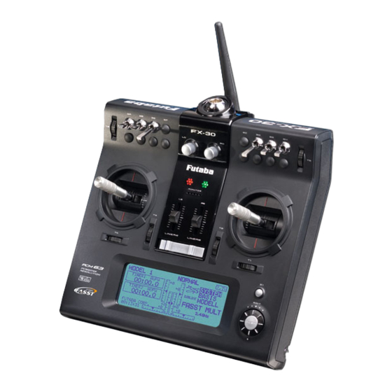
- Page 1 O P E R AT I N G I N S T R U C T I O N S FX-30 No. F 8042 35 MHz No. F 8043 40 MHz No. F 8044 41 MHz...
-
Page 2: Table Of Contents
Order No. FX-30 35 MHz: F 8042 40 MHz: F 8043 41 MHz: F 8044 Contents Section................Page Section................Page 11.1 Trainer mode ............22 Safety notes..............3 • Trainer mode: Teacher transmitter......23 Set contents .............4 • Trainer mode: Pupil transmitter ......23 General description ..........5 11.2 Screen settings............24 FX-30 transmitter ............5... -
Page 3: Safety Notes
If a unit gets wet or is damaged in a crash, it should not be used again even after you have dried it out and checked it tho- roughly. The only safe course of action is to replace damaged items, or at least have them checked by a robbe Service Centre. -
Page 4: Set Contents
Do not fly in any way which could endanger humans or the components and accessories which we expressly recom- animals. mend, and always use genuine robbe-Futaba connectors. It is • Never fly close to high-tension overhead cables or resi- not permissible to make modifications of any kind to the sys- dential areas. -
Page 5: General Description
Order No. FX-30 35 MHz: F 8042 40 MHz: F 8043 41 MHz: F 8044 GENERAL DESCRIPTION • The FX-30 transmitter features the new Rotary Trim System, The FX-40 is a high-class radio control system which sets new which combines the traditional method of operation with standards in many areas. -
Page 6: Specification
Order No. 35 MHz: F 8042 FX-30 40 MHz: F 8043 41 MHz: F 8044 3. SPECIFICATION FX-30 transmitter R-1410 DP PCM-1024 RECEIVER Control channels: ....8 - 12 channels FM No. -
Page 7: Rc Charger, Charging The Transmitter Battery
If this should occur, • The theoretical useful life of a Lithium cell when operated at cease using the transmitter and send it to your nearest robbe low discharge currents is around 500 charge / discharge Service Centre. -
Page 8: Inserting / Replacing The Rf Module
Order No. 35 MHz: F 8042 FX-30 40 MHz: F 8043 41 MHz: F 8044 CONVERTING THE THROTTLE FUNCTION INSERTING / REPLACING THE RF MODULE As supplied, the transmitter is set up in Universal mode, i.e. both sticks have a self-neutralising action. Most users will wish to convert one of the two sticks to a rat- chet or brake function in the vertical plane, to produce a non- neutralising function for the throttle channel. -
Page 9: Sd Card Memory Module
Utility” is available for viewing and erasing these files. It can be Model data relating to the various models downloaded from the Download area of the robbe Support can be stored on an SD card (max. capaci- Server at http://Support.robbe.com. -
Page 10: Trainer (Teacher - Pupil Mode) Mode
The FX-30 transmitter can be operated either as the Teacher transmitter or as the Pupil transmitter in combination with a huge variety of transmitters from the robbe / Futaba range. The follo- Trainer (teacher / pupil) mode operations make it possible for wing combinations are possible;... -
Page 11: Input Elements
Order No. 35 MHz: F 8042 FX-30 40 MHz: F 8043 41 MHz: F 8044 To operate a flight simulator program using the FX-30 trans- 4.10 LED STATUS mitter you will need to use the adaptor lead, No. 8239, which On the front panel you will Monitor-LED is available as an optional accessory. -
Page 12: Rotary Knobs
Order No. 35 MHz: F 8042 FX-30 40 MHz: F 8043 41 MHz: F 8044 4.12 ROTARY KNOBS 4.14 AERIAL The rotary knobs LD and RD are analogue controls which can be assigned freely to any function. They feature a fine centre The transmitter aerial is located in a compartment at the bot- detent, and the transmitter emits an audible signal when they tom of the transmitter case on the right-hand side, as seen... -
Page 13: Connecting The Servos
Order No. 35 MHz: F 8042 FX-30 40 MHz: F 8043 41 MHz: F 8044 CONNECTING SERVOS - PCM 1024 AND PCM 2048 (G3) Connecting servos and power supply: R 1410 DP receiver Socket: 10/B = receiver battery or servo for 10th channel, using Y-lead if necessary Outputs 1 …... -
Page 14: Fixed-Wing Model Aircraft, Normal Elevator
Order No. FX-30 35 MHz: F 8042 40 MHz: F 8043 41 MHz: F 8044 1). Airplanes, Motorglider and Glider with standard T-, Cross- and V-tail 1 Aileron 2 Aileron 2 Aileron+1 Flap Airplane EP-Glider Glider Airplane EP-Glider Glider Airplane EP-Glider Glider Elevator... - Page 15 Order No. FX-30 35 MHz: F 8042 40 MHz: F 8043 41 MHz: F 8044 2). Modeltype with 2 separate Elevator flaps, usable also as Aileron (Ailvator) 1 Aileron 2 Aileron 2 Aileron + 1 Flap Airplane EP-Glider Glider Airplane EP-Glider Glider Airplane...
-
Page 16: Fixed-Wing Model Aircraft, Separate (Two) Elevators15 5.4 Flying Wing Model Aircraft
Order No. FX-30 35 MHz: F 8042 40 MHz: F 8043 41 MHz: F 8044 3). Flying wing models as motorplane, EP-Glider ore Glider, standard rudder or winglet rudder 2 Aileron 2 Aileron + 1 Flap 2 Aileron + 2 Flap Airplane EP-Glider Glider... -
Page 17: Model Helicopters
Order No. FX-30 35 MHz: F 8042 40 MHz: F 8043 41 MHz: F 8044 4. Function sequence for Helicopter use H1 + 2, HE3 90°, HR3 120° Heli 4 HN3 120°, H3 140° Throttle Throttle Rudder Rudder Gyro Aileron Aileron Elevator Elevator... -
Page 18: Switching The Transmitter On And Off
Order No. FX-30 35 MHz: F 8042 40 MHz: F 8043 41 MHz: F 8044 SWITCHING THE TRANSMITTER ON / OFF CHANGING THE SPOT FREQUENCY • Locate the switch on the transmitter marked “Power”, and The system incorporates a DD Synthesizer system which slide it to the right. - Page 19 Order No. FX-30 35 MHz: F 8042 40 MHz: F 8043 41 MHz: F 8044 • The monitor LED on the receiver will now flash once, and a servo connected to channel 1 moves briefly around the centre point three times; this indicates that the receiver has picked up the signal and switched its frequency appropri- ately.
-
Page 20: Changing The Frequency Band And Modulation
• Use the ‘3-D hot-key’ to move to the ‘Modulation’ line. Robbe Modellsport accepts no liability for such combinations. Confirm your choice with ‘EDIT’, then select the desired modulation and spot frequency. Confirm the security query, then press the 3-D hot-key (‘EDIT’ button) to confirm... -
Page 21: Description Of The Start Screen
Order No. FX-30 35 MHz: F 8042 40 MHz: F 8043 41 MHz: F 8044 DESCRIPTION OF THE START SCREEN The most important information relating to the transmitter pro- gramming is displayed on the Start screen. At the same time most of the display fields also constitute the starting point for the individual programming procedures. -
Page 22: Menu Structure, Method Of Navigation
Section 4.7 on page 10 of these instructions lists the other transmitters from the robbe / Futaba range which can be used in combination with the FX-30 transmitter, acting either as the Hold the S1 button pressed in for at least 0.6 second to... -
Page 23: Trainer Mode: Teacher Transmitter
This channel is not transferred to the Pupil transmitter; it is T12FG, T14MZ, FX-30 or FX-40. controlled exclusively by the Teacher. • Eight channels for any other type of Futaba or robbe / Fut- • FUNC: aba transmitter. In this mode the corresponding channel is transferred to the Pupil transmitter. -
Page 24: Screen Settings
Order No. FX-30 35 MHz: F 8042 40 MHz: F 8043 41 MHz: F 8044 11.2 SCREEN (DISPLAY) SETTINGS 11.3 SYSTEM TIME In this menu you can select either of two different timers: In the ‘DISPLAY’ set-up menu you can alter the contrast set- 1) TOTAL: this timer displays the overall elapsed operating tings for the LCD screen. -
Page 25: User's Name
Order No. FX-30 35 MHz: F 8042 40 MHz: F 8043 41 MHz: F 8044 11.5 TRANSMITTER CONTROL SETTINGS 11.4 USER NAME Hardware transmitter control reverse This function is used to program your own name. This menu provides a means of reversing any of the transmit- ter controls, including the primary sticks and switches (hard- USER NAME Mark the User Name field and confirm with EDIT;... -
Page 26: Information
Order No. FX-30 35 MHz: F 8042 40 MHz: F 8043 41 MHz: F 8044 It is also possible to swap over the two-position and three- BASE MENU position switches. The functions of the Base Menu are described in detail in the following section. -
Page 27: Servo Monitor (Travel Indicator)
Order No. FX-30 35 MHz: F 8042 40 MHz: F 8043 41 MHz: F 8044 12.1 SERVO MONITOR 12.2 SELECTING A MODEL MEMORY The Servo Monitor menu displays all servo travels in a clear This menu enables you to select the actual model memory file form using a bar graph and percentage values. -
Page 28: Erasing A Model Memory
Order No. FX-30 35 MHz: F 8042 40 MHz: F 8043 41 MHz: F 8044 • At this point a security query appears which you must also COPYING A MODEL MEMORY confirm with EDIT. The new model memory is now activa- You can copy a model memory within the same memory ted. -
Page 29: Selecting The Model Type
Order No. FX-30 35 MHz: F 8042 40 MHz: F 8043 41 MHz: F 8044 12.3 SELECTING THE MODEL TYPE SELECTING THE WING AND TAIL TYPE If you have selected the Fixed-wing model type (power model This is the menu where you select the model type, the wing or glider), then the next step is to determine the appropriate type and the tail type for fixed-wing model aircraft. -
Page 30: Selecting The Swashplate Type
Order No. FX-30 35 MHz: F 8042 40 MHz: F 8043 41 MHz: F 8044 SELECTING THE SWASHPLATE TYPE 12.4 SELECTING THE FREQUENCY AND MODULATION If you have selected a model helicopter as model type, the This menu has already been described in detail in Sections 7 next step is to define the method of actuating the swashplate. -
Page 31: Function
Order No. FX-30 35 MHz: F 8042 40 MHz: F 8043 41 MHz: F 8044 12.5 FUNCTION • Then mark the appropriate function field, e.g. ‘ELEVATOR’ The transmitter employs a new method of selecting the model for elevator, and confirm it. type as basis for the mixer functions and transmitter control •... -
Page 32: Virtual Channels
Order No. FX-30 35 MHz: F 8042 40 MHz: F 8043 41 MHz: F 8044 • Trim Mode 12.6 SERVO CENTRE OFFSET Once you have marked and confirmed this field, you can set any of the following trim modes by turning the ‘3-D hot- When you install the servos in a model, it is always best to key’. -
Page 33: Servo Reverse
Order No. FX-30 35 MHz: F 8042 40 MHz: F 8043 41 MHz: F 8044 12.7 SERVO REVERSE 12.8 FAIL-SAFE SETTINGS This function is used to reverse the direction of servo rotation This function is only available in PCM-G3 and PCM-1024 electronically;... -
Page 34: Servo Travel Settings (Atv)
Order No. FX-30 35 MHz: F 8042 40 MHz: F 8043 41 MHz: F 8044 You can use exactly the same procedure to program the 12.9 SERVO TRAVEL SETTINGS (ENDP. ATV) Battery Fail-safe feature, separately for each channel. accomplish this you have to select ‘BAT-F/S’ in the right-hand This function provides a means of field by turning the ‘3-D hot-key’: the display now changes adjusting servo travel separately for... -
Page 35: Motor Cut Function (Motor Off)
Order No. FX-30 35 MHz: F 8042 40 MHz: F 8043 41 MHz: F 8044 12.10 MOTOR CUT FUNCTION 12.11THROTTLE PRE-SELECT (IDLE 2) This function enables you to cut The ‘Idle 2’ function enables the pilot to use a physical switch the motor using a switch, without as a rapid method of selecting a pre-set throttle position in the changing the idle trim. -
Page 36: Swashplate Settings
Order No. FX-30 35 MHz: F 8042 40 MHz: F 8043 41 MHz: F 8044 12.13SWASHPLATE SETTINGS This function is used to program the mixer functions required to actuate the swashplate of a model helicopter. It is not avai- lable if you select the swashplate type SWH1, as no mixers are required for the collective pitch function with this configura- tion. -
Page 37: Timer / Stopwatch Settings
Order No. FX-30 35 MHz: F 8042 40 MHz: F 8043 41 MHz: F 8044 The next step is to set up compensation for the pitch-axis 12.14 TIMER SETTINGS (stopwatch) function. Set the compensation value for that function in such a way that there is no adverse effect on the collective The Timer menu is used to set up and adjust the electronic pitch and roll functions at full travel of the pitch-axis stick. -
Page 38: Trim Display
Order No. FX-30 35 MHz: F 8042 40 MHz: F 8043 41 MHz: F 8044 • Selecting the switch 12.15 TRIM DISPLAY With the timer configured in this way, you can move on to defining the switches which are to be used to control the Use the 3-D hot-key in the Base menu to mark the “Trim dis- timers. -
Page 39: Data Reset
Order No. FX-30 35 MHz: F 8042 40 MHz: F 8043 41 MHz: F 8044 12.16 DATA RESET 12.17 FLIGHT MODE HOLD When you wish to enter the essential data for a new model, The purpose of this function is to enable you to change the you will often need to start by erasing the contents of a model settings in a flight mode other than the current one. -
Page 40: Model Menu
Order No. FX-30 35 MHz: F 8042 40 MHz: F 8043 41 MHz: F 8044 MODEL MENU 13.1 FLIGHT MODE The Model menu, which is described in detail in this section, The software of the FX-30 provides up to eight flight modes for provides functions which enable you to enter wide-ranging each individual model memory. - Page 41 Order No. FX-30 35 MHz: F 8042 40 MHz: F 8043 41 MHz: F 8044 • Erasing flight modes • Changing priorities Use the 3-D hot-key to mark the flight mode in the list Use the 3-D hot-key in the list to mark the flight mode which you wish to erase;...
-
Page 42: Transmitter Control Travel Settings (Afr)
Order No. FX-30 35 MHz: F 8042 40 MHz: F 8043 41 MHz: F 8044 13.2 TRANSMITTER CONTROL TRAVEL SETTINGS In this menu the servo speed can also be adjusted in the ‘Speed’ field. The first facility at this point is to program a The transmitter control travel (AFR) settings are used to adjust mode (linear or non-symmetrical). -
Page 43: Dual Rate Settings
Order No. FX-30 35 MHz: F 8042 40 MHz: F 8043 41 MHz: F 8044 To set up a freely variable curve you have to define curve 13.3 DUAL RATE SETTINGS points. The two screen shots show sections of the display as examples of these curves. -
Page 44: Programmable Mixers (Prog Mix)
Order No. FX-30 35 MHz: F 8042 40 MHz: F 8043 41 MHz: F 8044 13.4 PROGRAMMABLE MIXERS You move to the actual programming masks by marking the appropriate field in the ‘Mixer’ column on the left, and confir- The FX-30 features ten freely programmable mixers which are ming with the ‘EDIT’... - Page 45 Order No. FX-30 35 MHz: F 8042 40 MHz: F 8043 41 MHz: F 8044 • If the ‘Link’ function is switched on, the second mixer will The mixer rate is 0% at the left end-point of the affect the existing mixer, with the result that both aileron transmitter control.
- Page 46 Order No. FX-30 35 MHz: F 8042 40 MHz: F 8043 41 MHz: F 8044 First determine the ‘Slave’ channel or channels, i.e. the chan- A delay time can be programmed using virtually the same pro- nel into which a fixed value is to be mixed. Up to four functions cedure.
-
Page 47: Model Menu (Fixed-Wing Model Aircraft)
Order No. FX-30 35 MHz: F 8042 40 MHz: F 8043 41 MHz: F 8044 MODEL MENU (FIXED-WING MODEL AIRCRAFT) 14.1 AILERON DIFFERENTIAL In this Section we analyse the settings which are specific to Differential aileron travel is often required on fixed-wing model fixed-wing model aircraft. -
Page 48: Flap Settings
Order No. FX-30 35 MHz: F 8042 40 MHz: F 8043 41 MHz: F 8044 These are the individual steps for programming aileron diffe- 14.2 FLAP SETTINGS rential: This menu is • Enter the differential travels used for ente- Mark the appropriate adjustment field for the left and right ring the set- side of the aileron servos (max. -
Page 49: Aileron -> Flap Mixer
Order No. FX-30 35 MHz: F 8042 40 MHz: F 8043 41 MHz: F 8044 14.3 AILERON -> FLAP MIXER 14.4 AILERON -> BRAKE FLAP MIXER This menu is This menu is used to set the used for setting values mixer mixer which... -
Page 50: Aileron -> Rudder Mixer
Order No. FX-30 35 MHz: F 8042 40 MHz: F 8043 41 MHz: F 8044 14.5 AILERON -> RUDDER MIXER A mixer curve can be set up and programmed on the first page of the menu using the usual procedure. This menu is used for setting This mixer curve determines the rate of following, i.e. -
Page 51: Airbrake -> Elevator Mixer
Order No. FX-30 35 MHz: F 8042 40 MHz: F 8043 41 MHz: F 8044 14.6 AIRBRAKE -> ELEVATOR MIXER As ever, this mixer function must first be activated in the ‘ACT / INA’ line: first mark the field, enter the setting using the ‘3-D This menu hot-key’, and conclude the activation with EDIT. -
Page 52: Rudder -> Aileron Mixer
Order No. FX-30 35 MHz: F 8042 40 MHz: F 8043 41 MHz: F 8044 14.7 RUDDER -> AILERON MIXER 14.8 SPOILER This menu is The purpose of Chip Chip used for setting this menu is to aileron Winglet Winglet aileron mixer set up a mixer... -
Page 53: Spoiler Mixer
Order No. FX-30 35 MHz: F 8042 40 MHz: F 8043 41 MHz: F 8044 The function must first be activated in the ‘ACT / INA’ line, as 14.9 CAMBER-CHANGING FLAP -> ELEVATOR MIXER previously described: first mark the field, enter the settings using the ‘3-D hot-key’, and conclude the activation with EDIT. -
Page 54: Flap -> Elevator Mixer
Order No. FX-30 35 MHz: F 8042 40 MHz: F 8043 41 MHz: F 8044 14.11 CROW (BUTTERFLY) MIXER The effects and settings for the programming of ‘Global’ or ‘Separate’ mode have already been described repeatedly; The purpose of they are altered in the ‘Mode’ line. Chip Chip this menu is to... -
Page 55: Trim Mixer 1 And 2
Order No. FX-30 35 MHz: F 8042 40 MHz: F 8043 41 MHz: F 8044 The mixer rates are set in the main Crow menu for the (max.) 14.12 TRIM MIXER 1 AND 2 four aileron and flap servos, according to the selected model or wing type, using the familiar method. - Page 56 Order No. FX-30 35 MHz: F 8042 40 MHz: F 8043 41 MHz: F 8044 You can also determine whether the ‘TRIM’ mixer is to be acti- vated using the selected switch, or automatically by the posi- tion of one of the sticks. If you prefer the latter automatic mode, first mark the field and confirm with EDIT.
-
Page 57: Brake Flap Mixer
Order No. FX-30 35 MHz: F 8042 40 MHz: F 8043 41 MHz: F 8044 14.13 BRAKE FLAP MIXER (only available if suitable model type is selected) Chip Chip The purpose of aileron aileron this menu is to (AIL3) (AIL4) set the travels for all wing and tail control sur-... -
Page 58: Gyro Settings
Order No. FX-30 35 MHz: F 8042 40 MHz: F 8043 41 MHz: F 8044 14.14 GYRO SETTINGS 14.15 V-TAIL MIXER Gyros are often used in modern fixed-wing model aircraft in This menu presents all the mixer order to stabilise one flight axis, and this is the menu to use for functions required for controlling entering the settings for the gyro. -
Page 59: Elevators With Aileron Function
Order No. FX-30 35 MHz: F 8042 40 MHz: F 8043 41 MHz: F 8044 14.16 ELEVATORS WITH AILERON FUNCTION 14.17 WINGLET RUDDER SETTINGS This menu presents all the mixer This menu pre- functions required for controlling sents a pair of elevators which are also mixer functions used generate... -
Page 60: Electric Motor Settings
Order No. FX-30 35 MHz: F 8042 40 MHz: F 8043 41 MHz: F 8044 14.18 ELECTRIC MOTOR SETTINGS 14.19 RUDDER -> ELEVATOR MIXER (for power models only) The purpose of this menu is to enter the settings for switching The purpose of this mixer is to cause the elevator to deflect up an electric motor on and off;... -
Page 61: Snap Roll Function
Order No. FX-30 35 MHz: F 8042 40 MHz: F 8043 41 MHz: F 8044 14.20 SNAP ROLL FUNCTION The snap roll function enables you to define transmitter control The familiar method is employed: first mark the field, then positions which cause the aeroplane to carry out a particular change the value using the ‘3-D hot-key’... -
Page 62: Model Menu (Model Helicopter)
Order No. FX-30 35 MHz: F 8042 40 MHz: F 8043 41 MHz: F 8044 MODEL MENU (MODEL HELICOPTER) 15.1 COLLECTIVE PITCH CURVE SETTINGS This Section analyses the settings which are specific to model Operating the collective pitch stick moves the collective pitch helicopters, i.e. - Page 63 Order No. FX-30 35 MHz: F 8042 40 MHz: F 8043 41 MHz: F 8044 To be able to set different collective pitch curves it is essenti- • Trimming the collective pitch function al to switch each flight mode from group mode (GLOBAL) to The collective pitch trim can be optimised in the two single mode (SEPARATE).
-
Page 64: Throttle Curve Settings
Order No. FX-30 35 MHz: F 8042 40 MHz: F 8043 41 MHz: F 8044 15.2 THROTTLE CURVE SETTINGS To be able to set different throttle curves it is essential to switch each flight mode from group mode (GLOBAL) to single Operating the throttle stick moves the throttle servo, but also mode (SEPARATE). -
Page 65: Acceleration Function
Order No. FX-30 35 MHz: F 8042 40 MHz: F 8043 41 MHz: F 8044 15.3 ACCELERATION FUNCTION 15.4 AUTO-ROTATION SETTINGS The purpose of this function is to prevent unwanted changes This option is used for entering the settings for auto-rotation, in the helicopter’s attitude when you alter the throttle setting or so that the motor either stops or idles when the ‘Auto-rotation’... -
Page 66: Swashplate Mixer
Order No. FX-30 35 MHz: F 8042 40 MHz: F 8043 41 MHz: F 8044 The next step is to set the carburettor position for auto-rota- 15.5 SWASHPLATE MIXER tion, in the form of a percentage figure in the bottom line. In ‘Motor off’... -
Page 67: Throttle / Motor Mixer
Order No. FX-30 35 MHz: F 8042 40 MHz: F 8043 41 MHz: F 8044 15.6 THROTTLE / MOTOR MIXER This function is used to program a mixer which affects the The mixer function itself is actually set up in the sub-menu, position of the throttle servo when a ‘pitch-axis’... -
Page 68: Collective Pitch -> Needle Valve Mixer
Order No. FX-30 35 MHz: F 8042 40 MHz: F 8043 41 MHz: F 8044 15.7 COLLECTIVE PITCH -> NEEDLE VALVE MIXER 15.8 COLLECTIVE PITCH -> TAIL ROTOR (REVOLUTION) MIXER This function is used to program an automatic needle valve adjustment which follows the movement of the collective pitch The purpose of this function is to detect torque fluctuations at stick. -
Page 69: Gyro Settings
Order No. FX-30 35 MHz: F 8042 40 MHz: F 8043 41 MHz: F 8044 vertical (yaw) axis when you reduce motor torque or the colle- Under ‘FINE Trim’ you can enter the fine-tuning settings. A ctive pitch setting. transmitter control can be defined which is used as a means of fine-tuning the mixer settings: first select your preferred trans- An acceleration function can be programmed on the second mitter control in the ‘Transmitter control’... -
Page 70: Speed Governor (Regulator) Settings
Order No. FX-30 35 MHz: F 8042 40 MHz: F 8043 41 MHz: F 8044 15.10 SPEED GOVERNOR (REGULATOR) SETTINGS speed in rpm. This function enables you to adjust the settings of a speed governor (regulator) from the transmitter, and / or call up pre- To change this, simply mark the field, carry out the change set values. -
Page 71: Transmitter Control / Switch Select Menu
Order No. FX-30 35 MHz: F 8042 40 MHz: F 8043 41 MHz: F 8044 TRANSMITTER CONTROL / SWITCH SELECT MENU • ON / OFF The software of the FX-30 includes a comprehensive At this menu point you can define the direction of switching: Transmitter Control Select menu, which allows you to select NORMAL or REVERSE. -
Page 72: Updating The Transmitter Software
The user can replace the FX-30 software with the current ver- displayed on-screen: sion at any time. Update files are stored on the robbe website ready for downloading. We recommend that you register at http://support.robbe.com, so that you will be informed by e- mail newsletter of the availability of new updates. -
Page 73: Tips For Installing The Receiving System
Order No. FX-30 35 MHz: F 8042 40 MHz: F 8043 41 MHz: F 8044 amplify each other (timing differences between the two waves). TIPS ON INSTALLING THE RECEIVING SYSTEM Indoor flying - in sports halls, for example - often takes place in buildings of steel or steel-reinforced concrete construction, In the last few years the technical equipment carried in our where multiple reflections (roof - floor - walls) can very often... -
Page 74: Receiver Aerial
Order No. FX-30 35 MHz: F 8042 40 MHz: F 8043 41 MHz: F 8044 when connected to auxiliary electronic modules such as 18.1 RECEIVER AERIAL glowplug energizers, turbine control units, telemetry sys- The receiver aerial is conne- tems, GPS, etc. If you experience problems, once again we cted permanently to the recommend that you try using the suppressor filter, No. -
Page 75: Installing Servos
41 MHz: F 8044 18.5 INSTALLING SERVOS A range of different servo output arms is available for robbe When installing servos in a model, always use the rubber servos, and they are illustrated in the picture at the bottom of grommets and tubular brass spacers (eyelets) supplied. -
Page 76: The System In Use
Keep the receiving system as far away as possible All robbe-Futaba receivers continue to work with full range at from any ignition system. reduced voltage, down to the point where the supply voltage falls to 3 V. -
Page 77: Guarantee
21. LIABILITY EXCLUSION control systems for models operating in the frequency bands We at robbe Modellsport are not in a position to ensure that of 27 MHz, 35 MHz and 40 MHz do not need to be registered you observe the operating instructions, and have no influen-... -
Page 78: Recommended Accessories
Order No. FX-30 35 MHz: F 8042 40 MHz: F 8043 41 MHz: F 8044 ACCESSORIES Receiver battery charge lead T12FG transmitter battery No. F 1416 charge lead No. 8260 Adaptor lead for use with Trainer lead No. F 1591 flight simulators No. -
Page 79: Programming Sequence - Fixed-Wing Model Aircraft
Order No. FX-30 35 MHz: F 8042 40 MHz: F 8043 41 MHz: F 8044 Programming sequence - fixed-wing model aircraft Set the model type: • Select FAILSAFE in the Base menu. • Select MODEL SELECT in the Base menu. •... -
Page 80: Programming Sequence - Model Helicopters
Order No. FX-30 35 MHz: F 8042 40 MHz: F 8043 41 MHz: F 8044 Programming sequence - model helicopters Set the model type: • Select MOTOR CUT in the Base menu. • Select MODEL SELECT in the Base menu. •... - Page 81 Order No. FX-30 35 MHz: F 8042 40 MHz: F 8043 41 MHz: F 8044 Setting up the swashplate mixer In the Base menu select the Swashplate menu, then the sub- If you have selected a model with an electronic three-point menu Swashplate Detail.
-
Page 82: Disposal
Denmark MAAETOFT DMI 8900 RANDERS 0045-86-43 6100 0045-86-43 7744 Germany robbe-Service Metzloser Str. 36 D-36355 Grebenhain 0049-6644-87-777 0049-6644-7412 England robbe-Schlüter UK LE10-1UB Leicestershire 0044-1455-63 7151 0044-1455-63 5151 France S.A.V Messe BP 12 F-57730 Folschviller 0033-387-94 6258 0033-387-94 6258 Greece TAG Models Hellas... - Page 83 Order No. FX-30 35 MHz: F 8042 40 MHz: F 8043 41 MHz: F 8044 For your notes...
- Page 84 Copyright robbe Modellsport 2008 This document may not be copied or reproduced in whole or in part without the prior written approval of robbe Modellsport GmbH & Co. KG robbe Modellsport GmbH & Co.KG Metzloser Strasse 36 D-36355 Grebenhain...
Need help?
Do you have a question about the Futaba FX-30 and is the answer not in the manual?
Questions and answers