Advertisement
Quick Links
Download this manual
See also:
Service Manual
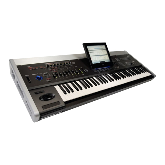
OASYS 76 / OASYS 88
Part2 Appendix
CONTENTS
(APPENDIX)
PARTS DIAGRAMS
LCD
PAD
Joystick
Vector Joystick : Page 7
How to change OASYS 76 CD-RW unit : Page 8 - 9
How to change OASYS 88 CD-RW unit : Page 10 - 11
CAUTION : OASYS FRONTPANEL SHIELD FORM: 12
Using the OASYS Internal Calibration Application: 13
How to reach HDD: Page14-24
S S
e e
r r
v
i i
c c
e e
v
S
e
r
v
i
c
: Page 2 - 4
: Page 5
: Page 6
M M
an
u u
a a
l l
a
n
e
M
a
n
u
a
l
Issued date : Oct.12, 2006
5th Edition
Issued by : KORG INC.
Advertisement

Related Manuals for Korg OASYS 76


Summary of Contents for Korg OASYS 76
- Page 1 Joystick : Page 6 Vector Joystick : Page 7 How to change OASYS 76 CD-RW unit : Page 8 - 9 How to change OASYS 88 CD-RW unit : Page 10 - 11 CAUTION : OASYS FRONTPANEL SHIELD FORM: 12...
- Page 2 HARNESS 74.7mm HNS-3420 500545050910 FFC HNS- 3460 500550022800 LCD CABLE COVER 500550022700 2 KOC-F41210 LCD CABLE COVER 1 KOC-F41209 SCREW KLM-2425 × Ready-Made TAPE DRAWN CHECKED APPROVED MODEL TAPE W=26mm TAMURA LCD UNIT 1 TITLE TAPE W= 5mm KORG INC.
- Page 3 KOC-F41237 500641041933 GUIDE RESEPTOR 500641041932 KOC-C41406 HINGE ANGLE (BACK SIDE) KOC-C41405 SCREW FE B BZMC 3*6 500646099700 HINGE COVER 500500035900 KOC-E40638 HINGE CUSHION KOC-F41208 HEXAGON SOCKET HEAD SCREW 4*10 DRAWN CHECKED APPROVED MODEL TAMURA LCD UNIT 2 TITLE KORG INC.
- Page 4 500641041951 LCD FRAME A ASSY KOC-H30290 500646099600 500641041947 KOC-E40641 LCD FRAME D KOC-C30684 DOUBLE-COATED ADHESIVE TAPE 500641041927 KORG PLATE 5 KOC-C41155-5 500641041946 500550022700 LCD FRAME C 500641041945 LCD CABLE COVER KOC-C30683-2 LCD FRAME B 1 KOC-F41209 KOC-C30683-1 SCREW SH0308BNI(AZUMA)3*8 500545050910...
- Page 5 PAD related parts 500646097500 50052500200 (NOTE) It is actually a magnet but 500646097700 PAD BUTTON it is wrongly listed as FERRITE PAD FRAME KOC-E40623 FERRITE CORE KOC-E30371-1 tear along perforation KLM-2417-91/2505-63 500646097600 PAD CUSSION KOC-E30375 200046362421 PCB ASSY KLM-2421/22/92/2651 200046362417 CLOSEUP PCB ASSY LED(pre-installed)
- Page 6 X-2160 JSPanel ASSY X-2100 JSPanel ASSY 500641041944 X-2100 EMI ANGLE JS KOC-C41410 KLM-2555(a part of KLM-2555(a part of 500475003438 200046362417 PCB ASSY 500641041944 200046362417 PCB HARNESS HNS-3438 KLM-2417-91/2505-63) X-2100 EMI ANGLE JS KOC-C41410 ASSY KLM-2417- 500475003450 500475003432 91/2505 63) HARNESS HNS-3450 HARNESS HNS-3432 2100 JoystickASSY 500641041905...
- Page 7 500641041908 500641041908 VN BZMC 9 VN BZMC 9 X-2100 VR PLATE KOC-C41378 X-2100 VR PLATE KOC-C41378 KLM-2304 VJS ASSY 500646096600 500641041907 500641041954 X-2100 JS GUIDE 1 500550023000 X-2100 JS GUIDE X-2100 JS PIN KOC-E40619 X-2100 JS MASK 2 KOC-C41379 KOC-C41418 KOC-F41056 500646096500 X-2100 JS SHAFT...
- Page 8 OASYS76 : CHANGE THE CD-RW 1.Open the front panel of OASYS76. Remove the screw of ‡ @ OP COVER, ‡ A EMI ANGLE 1 and ‡ B EMI ANGLE 2. 2.Remove the ‡ @ OP COVER, ‡ A EMI ANGLE 1 and ‡ B EMI ANGLE 2 . 3.Remove the 12 screws of the JOYSTICK-PANEL and KEYBOARD ASSY from the bottom side.
- Page 9 KEYBOARD ASSY. and remove the CD-RW UNIT. 5.Change the CD-RW.
- Page 10 OASYS88 : CHANGE THE CD-RW 1.Open the front panel of OASYS88. Remove the screw of ‡ @ OP COVER, ‡ A EMI ANGLE 1 and ‡ B EMI ANGLE 2. 2.Remove the ‡ @ OP COVER, ‡ A EMI ANGLE 1 and ‡ B EMI ANGLE 2 . 3.Remove 4 screws of the JOYSTICK-PANEL-ASSY from the bottom side.
- Page 11 4.Remove the cables , Remove the JOYSTICK-PANEL-ASSY. and remove the CD-RW UNIT. 5.Change the CD-RW.
- Page 12 CAUTION : OASYS FRONTPANEL SHIELD FORM The shield form is pasted to the front panel. (OASYS76 :4 pieces , OASYS88 :5 pieces) shield form shield form shield form shield form Please do not peel off the shield form when you insert the corner panel. Troubre occurs when the shield form falls in the PCB.
- Page 13 11.Vector Joystick: move all around, in a circle. performance, it will be necessary to re-calibrate. 12.Knobs, faders, and value slider: move each one to This is one of the reasons that Korg recommends its max and min positions. against formatting unless it is absolutely necessary.
- Page 14 How to reach HDD Open Page 1/5 Open the OASYS Drawn by H.Kudou Aug 21, 2006 (1) Remove 4 side screws. (2) Remove 7 rear screws. (3) Remove Rear cover. Open the Corner Panel. [Note] With a little support of pulling up the LCD will be a great help to Open/Close the Corner Panel.
- Page 15 Open Page 2/5 (1) Remove 5 screws. (2) Close the Corner Panel. [Note] Pulling up the LCD is effective when closing the Corner Panel,...
- Page 16 Open Page 3/5 (1) Tighten up 2 screws. (2) Open the Front Panel. PCB Cover OP Cover 2100 EMI Angle-2...
- Page 17 Open Page 4/5 (1) Remove 2 screws from OP cover. (2) Remove OP cover. (3) Remove 4 screws from PCB cover. Flip “2100 EMI Angle-2”.
- Page 18 Open Page 5/5 Remove PCB Cover. HDD is here.
- Page 19 Fixed with 4 screws.
- Page 20 How to reach HDD Close Page 1/5 Close the OASYS Be careful! Insert to set PCB Cover. Check Flip back “2100 EMI Angle-2”.
- Page 21 Close Page 2/5 Check if the PCB Cover has correctly been set. PCB Cover must be set under the Corner Panel. (1) Keep pushing PCB Cover toward the rear, tighten up 4 screws to PCB Cover (2) Set OP Cover. (3) Tighten up 2 screws to OP Cover tenderly.
- Page 22 Close Page 3/5 Check if the Harness has correctly been tied up. Check Close the Front Panel.
- Page 23 Close Page 4/5 (1) Remove 2 side screws. (2) Open Corner Panel. (1) Tighten up 5 screws. (2) Close the Corner Panel.
- Page 24 Close Page 5/5 (1) Set Rear cover. (2) Tighten up 7 rear screws. (3) Tighten up 4 side screws.
Need help?
Do you have a question about the OASYS 76 and is the answer not in the manual?
Questions and answers