Sony XR-1800 Service Manual
Fm/am/mw/lw/sw cassette car stereo
Hide thumbs
Also See for XR-1800:
- Operating instructions manual (25 pages) ,
- Service manual (35 pages) ,
- Instalation instructions (2 pages)
Table of Contents
Advertisement
QQ
3 7 63 1515 0
SERVICE MANUAL
TE
L 13942296513
www
.
MICROFILM
http://www.xiaoyu163.com
XR-1800/1803/1804
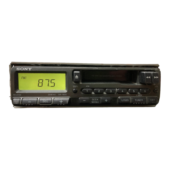
Photo: XR-1804
x
ao
u163
y
i
http://www.xiaoyu163.com
2 9
8
Model Name Using Similar Mechanism
Tape Transport Mechanism Type
SPECIFICATIONS
Q Q
3
6 7
1 3
1 5
FM/MW/LW CASSETTE CAR STEREO
FM/AM CASSETTE CAR STEREO
FM/MW/SW CASSETTE CAR STEREO
co
.
9 4
2 8
AEP Model
UK Model
E Model
East European Model
Saudi Arabia Model
MG-36SZ9-32
0 5
8
2 9
9 4
2 8
– Continued on next page –
XR-1800: AEP, UK Model/XR-1803
XR-1800: E Model
m
9 9
XR-1800
XR-1803
XR-1804
NEW
9 9
XR-1804
Advertisement
Table of Contents

Related Manuals for Sony XR-1800


Summary of Contents for Sony XR-1800
- Page 1 Model Name Using Similar Mechanism Tape Transport Mechanism Type MG-36SZ9-32 SPECIFICATIONS L 13942296513 – Continued on next page – XR-1800: AEP, UK Model/XR-1803 FM/MW/LW CASSETTE CAR STEREO XR-1800: E Model FM/AM CASSETTE CAR STEREO XR-1804 FM/MW/SW CASSETTE CAR STEREO u163 MICROFILM http://www.xiaoyu163.com...
-
Page 2: Table Of Contents
http://www.xiaoyu163.com 3 7 63 1515 0 TABLE OF CONTENTS GENERAL Button Locations ............. 3 Setting the Clock ............. 3 Installation ............... 4 Connections ..............4 DISASSEMBLY ............6 MECHANICAL ADJUSTMENTS ....... 10 ELECTRICAL ADJUSTMENTS Tape Deck Section ............10 Tuner Section ..............11 DIAGRAMS 5-1. - Page 3 http://www.xiaoyu163.com SECTION 1 This section is extracted from instruction manual. GENERAL 3 7 63 1515 0 L 13942296513 u163 – 3 – http://www.xiaoyu163.com...
- Page 4 http://www.xiaoyu163.com 3 7 63 1515 0 L 13942296513 u163 – 4 – http://www.xiaoyu163.com...
- Page 5 http://www.xiaoyu163.com 3 7 63 1515 0 L 13942296513 u163 – 5 – http://www.xiaoyu163.com...
-
Page 6: Disassembly
http://www.xiaoyu163.com SECTION 2 DISASSEMBLY 3 7 63 1515 0 Note: Follow the disassembly procedure in the numerical order given. COVER ASS’Y 3 cover ass’y L 13942296513 MECHANISM DECK BLOCK 1 two screws 1 two screws (PTT2.6 × 6) (PTT2.6 × 6) 2 connector 3 mechanism deck block (CN901) - Page 7 http://www.xiaoyu163.com 3 7 63 1515 0 MAIN BOARD, HEAT SINK 1 five screws (PTT2.6 × 8) 3 two screws 1 two screws (ground point) (PTT2.6 × 6) 2 heat sink 4 main board L 13942296513 MECHANISM DECK (MG-36SZ9-32) 3 mechanism deck (MG-36SZ9-32) 2 bracket (MD) u163...
- Page 8 http://www.xiaoyu163.com 3 7 63 1515 0 MOTOR ASS’Y (CAPSTAN/REEL) (M901) 2 belt 2 belt 1 two screws (P2 × 3) 3 motor ass’y (CAPSTAN/REEL) (M901) L 13942296513 CASSETTE HANGER (X) 1 Remove the claw toward direction. 4 two claws 5 cassette hanger 3 boss 3 boss 2 Remove the return link...
- Page 9 http://www.xiaoyu163.com 3 7 63 1515 0 CASSETTE HOLDER (X) 2 Removal the cassette holder (x) to direction of the arrow. 1 Push an arrow A part. L 13942296513 u163 – 9 – http://www.xiaoyu163.com...
-
Page 10: Mechanical Adjustments
http://www.xiaoyu163.com SECTION 3 SECTION 4 MECHANICAL ADJUSTMENTS 3 7 63 1515 0 ELECTRICAL ADJUSTMENTS 1. Clean the following parts with a denatured-alcohol-moistened TAPE DECK SECTION 0 dB= 0.775 V swab: playback head pinch roller 1. The adjustments should be performed in the order given in rubber belt capstan this service manual. -
Page 11: Tuner Section
4. Repeat the above adjustment for the REV PB mode. TUNER SECTION 5. Check that output level difference between FWD PB mode and REV PB mode is within 4 dB. XR-1800 E model, a tuner section is no adjustment. 0 dB=1 µV Adjustment Location: PB head Cautions during repair When the tuner unit is defective, replace it by a new one be- cause its internal block is difficult to repair. - Page 12 http://www.xiaoyu163.com 3 7 63 1515 0 FM Noise Focus Adjustment (XR-1804 only) MW Auto Scan/Stop Level Adjustment Setting: Setting: [TUNER] [TUNER] button: FM1 button: MW FREQUENCY SELECT switch: FM 50 k FREQUENCY SELECT switch: MW 9 k (XR-1804 only) FM RF signal level meter antenna jack (CN900) generator...
- Page 13 http://www.xiaoyu163.com 3 7 63 1515 0 Adjustment Location: – SET UPPER VIEW – Tape Speed Adjustment TU100 RV1 MW Auto Scan/Stop Level Adjustment RV2 FM Auto Scan/Stop Level Adjustment RV3 FM Noise Focus Adjustment RV4 FM Stereo Separation Adjustment CN901 L 13942296513 –...
-
Page 14: Diagrams
— Not used (open) Key matrix scan signal output terminal Used for the XR-1800: E model and XR-1804 Key matrix scan signal output terminal Not used (open) Key matrix scan signal output terminal Used for the XR-1800: AEP, UK models VOL-CE Chip enable signal output to the electrical volume (IC450) “H”... - Page 15 http://www.xiaoyu163.com 3 7 63 1515 0 Pin No. Pin Name Function Key matrix scan signal output terminal — Not used (open) LCD-CLK Serial data transfer clock signal output to the liquid crystal display driver (IC900) LCD-CE Chip enable signal output to the liquid crystal display driver (IC900) “H” active LCD-DATA Serial data output to the liquid crystal display driver (IC900) “H”...
-
Page 16: Note For Printed Wriring Boards And Schematic Diagrams
http://www.xiaoyu163.com 3 7 63 1515 0 5-2. NOTE FOR PRINTED WIRING BOARDS AND SCHEMATIC DIAGRAMS • Waveform Note on Schematic Diagram: 1 IC1 1 (XIN) • All capacitors are in µF unless otherwise noted. pF: µµF 50 WV or less are not indicated except for electrolytics and tantalums. -
Page 17: Printed Wiring Board - Main Section
XR-1800/1803/1804 5-3. PRINTED WIRING BOARD – MAIN Section – 3 7 6 3 1 5 1 5 0 • Semiconductor Location Ref. No. Location D100 D350 D351 D503 D506 D551 D600 D601 D602 D603 D605 D606 D607 D608 D609... -
Page 18: Schematic Diagram - Main Section (1/2)
XR-1800/1803/1804 5-4. SCHEMATIC DIAGRAM – MAIN Section (1/2) – • See page 16 for Waveform. 3 7 6 3 1 5 1 5 0 1 3 9 4 2 2 9 6 5 1 3 w w w u 1 6 3 –... -
Page 19: Schematic Diagram - Main Section (2/2)
XR-1800/1803/1804 5-5. SCHEMATIC DIAGRAM – MAIN Section (2/2) – • See page 27 for IC Block Diagram. 3 7 6 3 1 5 1 5 0 1 3 9 4 2 2 9 6 5 1 3 w w w u 1 6 3 –... -
Page 20: Printed Wiring Board - Panel Section
XR-1800/1803/1804 3 7 6 3 1 5 1 5 0 5-6. PRINTED WIRING BOARD – PANEL Section – • Semiconductor Location Ref. No. Location 1 3 9 4 2 2 9 6 5 1 3 5-7. SCHEMATIC DIAGRAM – PANEL Section –... - Page 21 http://www.xiaoyu163.com 3 7 63 1515 0 • IC Block Diagram – MAIN Board – IC450 LC75372E ROUT RVREF RVREF RVREF RVREF – – – RFIN TEST RVREF RVREF RFOUT – RROUT – SHIFT LATCH DECODER CONTROL REGISTER RVREF RVREF VREF RVREF LVREF –...
-
Page 22: Exploded Views
3-924-404-41 DOOR, CASSETTE (XR-1804) * 14 A-3313-751-A MAIN BOARD, COMPLETE (XR-1800: E) 3-377-892-01 SPRING (C DOOR), TORSION * 14 A-3313-844-A MAIN BOARD, COMPLETE (XR-1800: AEP, UK) 3-022-479-01 BRACKET (MD) * 14 A-3313-845-A MAIN BOARD, COMPLETE (XR-1803) 3-937-529-01 COVER (FF/REW) * 14... - Page 23 3-022-473-11 PANEL, FRONT (XR-1803) (DSPL. 1. 2. 3. 4. 5. 6. LCL) u163 3-022-473-21 PANEL, FRONT (XR-1804) LCD900 1-803-137-11 DISPLAY PANEL, LIQUID CRYSTAL (XR-1800) LCD900 1-803-138-11 DISPLAY PANEL, LIQUID CRYSTAL (XR-1804) * 59 3-022-471-01 PLATE (LCD), GROUND LCD900 1-803-139-11 DISPLAY PANEL, LIQUID CRYSTAL (XR-1803)
- Page 24 http://www.xiaoyu163.com 3 7 63 1515 0 (3) MECHANISM DECK SECTION-1 (MG-36SZ9-32) L 13942296513 not supplied not supplied S901 Ref. No. Part No. Description Remark Ref. No. Part No. Description Remark 3-938-660-01 LEVER, EJECT 3-392-954-01 SPRING 3-392-950-01 SPRING 3-392-994-01 ROLLER, PROGRAM 3-392-951-01 SPRING * 115 3-392-933-01 LEVER (B), CHANGE...
- Page 25 http://www.xiaoyu163.com 3 7 63 1515 0 (4) MECHANISM DECK SECTION-2 (MG-36SZ9-32) HP901 L 13942296513 Ref. No. Part No. Description Remark Ref. No. Part No. Description Remark 3-570-615-02 POLY-WASHER (DIA.1.2) 3-375-379-01 SCREW, AZIMUTH 3-392-945-01 ROLLER (A), H.P * 164 3-379-142-01 ARM (B), ADJUSTOR 3-392-942-01 ROLLER (B), H.P 3-392-984-02 GUIDE, TAPE 3-375-378-01 ARM (R) ASSY, PINCH...
- Page 26 http://www.xiaoyu163.com 3 7 63 1515 0 (5) MECHANISM DECK SECTION-3 (MG-36SZ9-32) L 13942296513 not supplied not supplied Ref. No. Part No. Description Remark Ref. No. Part No. Description Remark 3-392-959-01 SPRING 3-392-937-01 GEAR (B) 3-392-985-02 RATCHET 3-570-615-02 POLY-WASHER (DIA.1.2) * 203 4-908-792-11 SCREW (B2) 3-392-915-01 GEAR, IDLE 3-392-960-01 SPRING...
- Page 27 http://www.xiaoyu163.com 3 7 63 1515 0 (6) MECHANISM DECK SECTION-4 (MG-36SZ9-32) M901 S903 S902 not supplied L 13942296513 Ref. No. Part No. Description Remark Ref. No. Part No. Description Remark 3-392-967-01 BELT, MAIN 3-392-963-01 SPRING (R) 3-392-995-02 FLYWHEEL ASSY (BR) 3-318-204-91 SCREW (M1.7X4), TAPPING 3-375-375-02 BELT (C), SUB 3-375-376-01 MUTE (PWB) (MUTE SWITCH BOARD)
-
Page 28: Electrical Parts List
Description Remark KEY BOARD < LIQUID CRYSTAL DISPLAY > ********** LCD900 1-803-137-11 DISPLAY PANEL, LIQUID CRYSTAL (XR-1800) 3-022-466-01 REFLECTOR LCD900 1-803-138-11 DISPLAY PANEL, LIQUID CRYSTAL (XR-1804) 3-022-471-01 PLATE (LCD), GROUND LCD900 1-803-139-11 DISPLAY PANEL, LIQUID CRYSTAL (XR-1803) 3-022-482-01 PLATE (LCD), LIGHT GUIDE 3-024-264-01 ILLUMINATOR <... - Page 29 Part No. Description Remark A-3313-751-A MAIN BOARD, COMPLETE (XR-1800: E) C125 1-163-235-11 CERAMIC CHIP 22PF A-3313-844-A MAIN BOARD, COMPLETE (XR-1800: AEP, UK) (XR-1800: AEP, UK/1803) A-3313-845-A MAIN BOARD, COMPLETE (XR-1803) C131 1-126-162-11 ELECT 3.3uF A-3313-904-A MAIN BOARD, COMPLETE (XR-1804) C132 1-163-037-11 CERAMIC CHIP 0.022uF...
- Page 30 1-216-295-00 SHORT 0 (XR-1800: E) 8-719-991-33 DIODE 1SS133T-77 JC104 1-216-295-00 SHORT 8-719-991-33 DIODE 1SS133T-77 JC112 1-216-296-00 SHORT 8-719-991-33 DIODE 1SS133T-77 (XR-1800: AEP, UK) 8-719-991-33 DIODE 1SS133T-77 (XR-1800: E/1804) JC113 1-216-296-00 SHORT JC114 1-216-296-00 SHORT 8-719-109-93 DIODE RD6.2ES2 JC116 1-216-296-00 SHORT 8-719-109-93 DIODE RD6.2ES2...
- Page 31 1-216-295-00 SHORT 1-216-049-11 RES,CHIP 1/10W < COIL/RESISTOR > (XR-1800: E) 1-216-057-00 METAL CHIP 2.2K 1/10W L 13942296513 JW144 1-410-509-31 MICRO INDUCTOR 10uH (XR-1800: E) (XR-1804) 1-249-389-11 CARBON 1/4W 1-216-049-11 RES,CHIP 1/10W (EXCEPT 1804) 1-216-049-11 RES,CHIP 1/10W 1-410-513-11 MICRO INDUCTOR 22uH (XR-1804)
- Page 32 MAIN 3 7 63 1515 0 Ref. No. Part No. Description Remark Ref. No. Part No. Description Remark (EXCEPT XR-1800: E) R370 1-216-051-00 METAL CHIP 1.2K 1/10W R106 1-216-041-00 METAL CHIP 1/10W R371 1-216-073-00 METAL CHIP 1/10W R107 1-216-069-00 METAL CHIP 6.8K...
- Page 33 X-3366-405-1 SCREW ASSY (EXT), FITTING X-3371-913-1 SCREW ASSY (J) 1-776-207-41 CORD (WITH CONNECTOR) (POWER) 1-776-207-41 CORD (WITH CONNECTOR) (POWER) F901 1-532-877-11 FUSE (BLADE TYPE) (AUTO FUSE) (10A) 1-775-543-11 CORD, GROUND (XR-1800: E) HP901 1-543-717-11 HEAD, MAGNETIC (PLAYBACK) M901 X-3364-496-1 MOTOR ASSY (REEL/CAPSTAN) 3-018-384-01 COLLAR...
- Page 34 XR-1800/1803/1804 3 7 63 1515 0 L 13942296513 u163 Sony Corporation 98C0563-1 9-925-920-11 Personal & Mobile Communication Company Printed in Japan © 1998. 3 – 38 – Published by Quality Assurance Dept. http://www.xiaoyu163.com...
Need help?
Do you have a question about the XR-1800 and is the answer not in the manual?
Questions and answers