Table of Contents
Advertisement
Quick Links
SM41
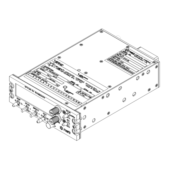
NPX138
PANEL MOUNT RADIO
INSTALLATION AND OPERATION MANUAL
REV 4.00 November 10, 2003
Northern Airborne Technology Ltd.
1925 Kirschner Road
Kelowna BC, Canada
V1Y 4N7
Telephone (250) 763-2232
Facsimile (250) 762-3374
Copyright 2003 by Northern Airborne Technology
CONFIDENTIAL AND PROPRIETARY TO NORTHERN AIRBORNE TECHNOLOGY LTD.
Advertisement
Table of Contents

Subscribe to Our Youtube Channel
Summary of Contents for Nat SM41
- Page 1 SM41 NPX138 PANEL MOUNT RADIO INSTALLATION AND OPERATION MANUAL REV 4.00 November 10, 2003 Northern Airborne Technology Ltd. 1925 Kirschner Road Kelowna BC, Canada V1Y 4N7 Telephone (250) 763-2232 Facsimile (250) 762-3374 Copyright 2003 by Northern Airborne Technology CONFIDENTIAL AND PROPRIETARY TO NORTHERN AIRBORNE TECHNOLOGY LTD.
-
Page 3: Important Information
SM41 Rev. 4.00 NPX138 Panel Mount Radio Manual IMPORTANT INFORMATION FOR AVIONICS INSTALLATION FACILITIES The NPX138 is supplied without TSO certification, as no such standard presently exists for airborne VHF/FM radio transceivers. This equipment provides what considered “supplemental” communications, and can be installed in an aircraft on a “Non interference”... - Page 5 SM41 Rev. 4.00 NPX138 Panel Mount Radio Manual Periodically NAT will release manual amendments. In order to maintain the most accurate and up to date manual these amendments should be carried out immediately upon receipt and recorded on the following amendment record.
- Page 7 INSTALL_OPS MANUAL AMENDMENT Manual: SM41 (NPX) Amendment #: 4 Document # SM41\Install_Ops\809-0004 Amendment Date: Jun 10, 2005 The purpose of this amendment is to add information relevant to the NPX138N-070. Amendment Instructions: Remove Pages Replace With Pages 1-5 Rev 4.00 1-5 Rev 4.00 Amendment # 4...
- Page 9 INSTALL_OPS MANUAL AMENDMENT Manual: Amendment #: 3 SM41 NPX138 Document # Amendment Date: SM41\Install_Ops\809-0003 Nov 22, 2004 The purpose of this amendment is to amend the cable and wiring specifications in line with Transport Canada requirements. Amendment Instructions: Remove Pages Replace With Pages 2-1 and 2-2 Rev 4.00...
- Page 11 INSTALL_OPS MANUAL AMENDMENT Manual: Amendment #: 2 SM41 NPX138 Document # Amendment Date: SM41\Install_Ops\809-0002 Aug 19, 2004 The purpose of this amendment is to update the faceplate drawing. Amendment Instructions: Remove Pages Replace With Pages 2-5 Amendment #2 Remove Drawings (Section 2) Replace or add Drawings (Section 2) NPX138\905-0 rev 1.40...
- Page 13 MANUAL AMENDMENT Manual: SM41 NPX138 Amendment #: 1 Document # SM41\Install_Ops\809-0001 Amendment Date: Apr 19, 2004 The purpose of this amendment is to include the new revision of the NPX138\634-0 in the manual. Amendment Instructions: Remove Page Replace With Page 2-5 rev 4.00...
-
Page 15: Table Of Contents
SM41 Rev. 4.00 NPX138 Panel Mount Radio Manual Table of Contents Section Title Page Description Introduction Purpose of Equipment Features Specifications 1.4.1 Electrical Specifications 1.4.2 Receiver 1.4.3 Transmitter 1.4.4 Physical Specifications 1.4.5 Environmental Specifications Unit Nomenclature 1.5.1 Narrowband Capability 1.5.2 Options 1.5.3... - Page 17 SM41 Rev. 4.00 NPX138 Panel Mount Radio Manual 3.4.2 RX/TX Status Indicator 3.4.3 Scan/Guard TX Switch 3.4.4 Guard Controls General Controls — Normal Operating Mode 3.5.1 Channel Switch 3.5.2 Brightness Switch 3.5.3 Squelch Pushbutton Channel Display 3.6.1 ID Display Line 3.6.2...
-
Page 19: Introduction
NPX138 series of panel mount FM transceivers, serial numbers 1238 and subsequent. The NPX138 incorporates NAT’s proven user-friendly operating system with on-line help, making it easy to program and use. The small size makes this radio ideal for airframes where size and weight are a factor. -
Page 20: Specifications
NPX138 Panel Mount Radio Manual SM41 Rev. 4.00 Specifications 1.4.1 Electrical Specifications Input power 28 Vdc nominal Current consumption 0.5 A receive/2.0 A transmit (typical) 0.8 A receive/3.0 A transmit (max.) Panel lighting 28 Vdc, 14 Vdc or 5 Vdc dependent on model. -
Page 21: Transmitter
SM41 Rev. 4.00 NPX138 Panel Mount Radio Manual 1.4.3 Transmitter RF power output 1 W/10 W Selectable 50 Ω nominal RF input/output impedance Rated System Deviation NPX138 (all models) ± 5.0 kHz max, limited NPX138N (all models) Wideband ± 5.0 kHz max, limited Narrowband ±... -
Page 22: Environmental Specifications
NPX138 Panel Mount Radio Manual SM41 Rev. 4.00 1.4.5 Environmental Specifications Operating temperature -30 C to +60 C Altitude 25,000 feet Humidity Vibration DO-160C, Cat. M Unit Nomenclature Variants of the NPX138 series radios are identified as follows: Narrowband Capability... -
Page 23: Voice Inversion Encryption
SM41 Rev. 4.00 NPX138 Panel Mount Radio Manual 1.5.3 Special Options The digit in the second position of the unit suffix indicates any special options installed. NPX138 N - 000 No Special options installed USFS Standard Guard Custom Guard - consult factory for details... -
Page 25: Introduction
Verify that all items are present before proceeding, and report any shortage immediately to your supplier. Complete the warranty card information, and send it to NAT when the installation is complete. If you fail to complete the warranty card, the warranty will be activated on date of shipment from NAT. -
Page 26: Notes
NPX138 Panel Mount Radio Manual SM41 Rev. 4.00 2.3.3 Notes The case of the NPX138 must be electrically grounded for maximum resistance to low frequency interference. A pin on the connector (Chassis ground) is provided and must be connected by a short wire to a clean ground, not jumpered to the power ground wire connection. -
Page 27: Antennas
SM41 Rev. 4.00 NPX138 Panel Mount Radio Manual minimum at the antenna. Avoid sharp bends in the coax cables (minimum 3" radius) to prevent severe reflections. If sharp bends are required, use 90° elbow adapters. Fabrication & installation of wiring harness should be in accordance with AC 43.13-1A chapter 11, sections 3 and 7. -
Page 28: Mechanical Mounting
NPX138 Panel Mount Radio Manual SM41 Rev. 4.00 2.3.6 Mechanical Mounting Installation of the transceiver should be in accordance with AC 43.13-1A chapter 2, section 3, and AC 43.13-2A, chapter 2. Pr 35 Dzus rail or equivalent may be used. -
Page 29: Post Installation Emi Test
SM41 Rev. 4.00 NPX138 Panel Mount Radio Manual 2.3.7.2 Power On Checks Install the NPX138 and power up the ship’s systems. Turn on the radio. Check the operation of all front panel controls. Adjust brightness and volume levels as required. - Page 31 Confidential and Proprietary to NAT...
- Page 37 INSTALLATION APPROVAL TEST PROCEDURE NAT Part #: NPX138 Description: Panel Mount Radio Document #: NPX138\634-0 Rev: 1.10 Post Installation EMI Test The purpose of this test is to identify any interference that the NPX138 may cause with existing aircraft systems.
- Page 38 NPX138 Installation Approval Test Procedure Results If the installed system passes all of the applicable EMI tests, then no further action is required. If interference is observed, then the interference must be assessed against the appropriate standards of airworthiness for the system in question. For example: it is permissible for a VFR certified GPS to lose navigation capability while the NPX138 is transmitting, providing that it recovers properly and promptly, but it is not permissible for an IFR Approach certified GPS to be affected in the same way.
- Page 39 NPX138 Installation Approval Test Procedure Determine if the image frequency for the VHF Comm falls within the range of the NPX138 unit. If so, select a set of frequencies that will cause the NPX138 to be set as close as possible to the image frequency. Any one of the many possible sets will suffice.
- Page 40 NPX138 Installation Approval Test Procedure Determine if the image frequency for the VOR/ILS Nav falls within the range of the NPX138 unit. If so, select two sets of frequencies that will cause the NPX138 to be set as close as possible to the image frequency. Choose one set in the localizer frequency range, and one in the VOR frequency range.
- Page 41 NPX138 Installation Approval Test Procedure Modulate the NPX138 transmitter on the following frequencies for at least 20 seconds. Look for any movement of flags or needles on the navigation display. FREQUENCIES RESULTS G/S #1 NPX138 PASS FAIL 334.7 (108.1) 167.3500 FREQUENCIES RESULTS G/S #2...
- Page 42 NPX138 Installation Approval Test Procedure Perform a coupled ILS approach to the aircraft's certified limits. Modulate the NPX138 transmitter on the above frequencies for at least 20 seconds. Observe any effect on the autopilot. Repeat for each different system such as ILS #2, GPS, FMS etc.
- Page 43 NPX138 Installation Approval Test Procedure STEP SYSTEM PASS FAIL NOTES NOTES: End of Installation Approval Test Procedure Rev. 1.10 Apr 19, 2004 Page 7 of 7 E NG-FORM: 634-0100.DOT CONFIDENTIAL AND PROPRIETARY TO NORTHERN AIRBORNE TECHNOLOGY LTD.
-
Page 49: Introduction
For ease of use and operability, NAT uses the same control layout and operating system in the NPX138 series of radios as it does in its popular Tac/Com family of radio control heads. -
Page 50: Initial Operating Display
NPX138 Panel Mount Radio Manual SM41 Rev. 4.00 3.2.2 Initial Operating Display If you decline ‘Help’ (by using the NEXT switch as directed), the radio will display a summary of the installed functions and current settings (this feature can be disabled at installation for faster start-up). -
Page 51: Function Controls
SM41 Rev. 4.00 NPX138 Panel Mount Radio Manual Function Controls The controls located to the right of the display are ‘Function’ controls. These controls access the radio functions most often used. Access to all other functions is via the status lines (see section 3.8 for further details on ‘Status Editing’). - Page 52 NPX138 Panel Mount Radio Manual SM41 Rev. 4.00 3.4.3 Scan/Guard TX Switch When this switch is in the SCAN position, the radio will begin scanning. See section 3.10 for further details on scanning. When this switch is in the GD TX position, all radio transmissions will be on the guard transmit frequency instead of the transmit frequency of the current channel.
- Page 53 SM41 Rev. 4.00 NPX138 Panel Mount Radio Manual General Controls — Normal Operating Mode Channel Switch Brightness Switch Edit Switch Squelch Pushbutton The General Controls are those labeled in the above diagram and affect the over-all operation of the radio. The position of the EDIT switch determines the operating mode of the radio.
- Page 54 NPX138 Panel Mount Radio Manual SM41 Rev. 4.00 3.5.3 Squelch Pushbutton Pressing the squelch test button over-rides all squelch logic, and lets the radio’s unsquelched audio receive signal pass to the aircraft’s audio system. The squelch test function is useful for monitoring activity on the radio when tones prevent the squelch from opening, or to verify volume settings or radio function.
- Page 55 SM41 Rev. 4.00 NPX138 Panel Mount Radio Manual 3.6.2 RX Display Line The RX line includes the channel number, the receive frequency and the receive tone. A typical RX line might look like this: 156.8750r Channel RX Freq. RX Tone The radio will receive incoming FM signals that have a carrier frequency equal to that of the receive frequency of the displayed channel.
- Page 56 NPX138 Panel Mount Radio Manual SM41 Rev. 4.00 Channel Editing Editing is the general term for changing any information stored in the NPX radio. There are two basic types of editing, all selectable from the front panel of the radio. These are ‘Channel editing’...
- Page 57 SM41 Rev. 4.00 NPX138 Panel Mount Radio Manual 3.7.1 SELECT Switch The SELECT switch steps the data entry up or down (+/-). The radio only permits a valid choice for each position selected for editing. This is to aid operators in reducing entry mistakes, particularly when busy with other flight procedures.
- Page 58 NPX138 Panel Mount Radio Manual SM41 Rev. 4.00 Sometimes, more than one character will flash. This is because the only valid choices involve multiple characters, such as the fractional kHz entry for a channel frequency. This is also true for tone code entries. The SELECT switch will slew through the available entries from an internal table.
-
Page 59: Nov 10, 2003
SM41 Rev. 4.00 NPX138 Panel Mount Radio Manual 3.8.1 NEXT and SELECT Switch Use Toggling SELECT will step to the previous/next available setting for the current function. To advance to the next function, toggle NEXT. Use the SELECT switch to again choose the desired setting, and continue in this manner until all the radio status lines contain desired information. - Page 60 NPX138 Panel Mount Radio Manual SM41 Rev. 4.00 • SCAN There are three scanning modes available for selection: LIST, PRIORITY, and LIST+PRI. See section 3.10 for further details on scanning. • P1 This is the Priority channel used in Priority and List+Priority Scanning. It can be set to any valid channel number, or if not required, can be set to NONE.
- Page 61 SM41 Rev. 4.00 NPX138 Panel Mount Radio Manual 3.9.2 Tone Display and Selection The NPX radio displays the tones for the selected channel on the last three positions (far right hand side) of the RX and TX lines. Use the Channel Edit mode to select and store the appropriate tones for each channel.
- Page 62 NPX138 Panel Mount Radio Manual SM41 Rev. 4.00 Table 1 below shows the four different display options for each of the available tones. Tone Frequency (Hz) 1-38 WCODE MCODE 67.0 71.9 74.4 77.0 79.7 82.5 85.4 88.5 91.5 94.8 97.4 100.0...
- Page 63 SM41 Rev. 4.00 NPX138 Panel Mount Radio Manual 3.9.3 Turning Tones On and Off The NPX radio also has the capability to have tones enabled or disabled globally. By editing the TONES status line, the operator can set all the tones ON, OFF or to TX ONLY.
- Page 64 NPX138 Panel Mount Radio Manual SM41 Rev. 4.00 3.10.2 Scan Operation Activate scanning by moving the SCAN/NORM/GUARD TX toggle switch to the SCAN position. The ‘home’ channel is the channel that the radio was on before scanning was activated. The radio scans the home channel and all channels on the ‘scan list’ at a maximum rate of 30 channels/second.
- Page 65 SM41 Rev. 4.00 NPX138 Panel Mount Radio Manual • LIST Scanning The second last space on each channel ID line indicates whether that channel is in the scan list or not. If it displays a dash ‘-’, the channel is not in the list. If the channel is in the list it displays the scan flag ( s c).
- Page 66 Incorrect Use Of This Mode May Render The Radio INOPERABLE! Use This Function With Extreme Care. If you have ANY questions, please phone NAT prior to use. To enter this mode, do the following, EXACTLY AS DESCRIBED: With the power turned off, lock the EDIT switch into the CH position.
- Page 67 SM41 Rev. 4.00 NPX138 Panel Mount Radio Manual Depending on the style of radio and the options selected, the information on this and subsequent screens will vary. Don't worry if all the features listed in the following table are not displayed.
Need help?
Do you have a question about the SM41 and is the answer not in the manual?
Questions and answers