Table of Contents
Advertisement
Advertisement
Table of Contents

Related Manuals for AMEC Camino-108


Summary of Contents for AMEC Camino-108
- Page 2 DISCLAIMER AMEC is devoted to publish and maintain this product manual. As we continue to improve our AIS products to satisfy all customers’ needs, information in this document is subject to change without notice. AMEC does not make any...
- Page 3 WARNING: While most of the installation can be performed by the owner or the crew, a final commissioning can be done by your local agent/dealer when needed or required. AMEC and the local agent/dealer will not bear any responsibilities over any damages resulted from improper installation by unauthorized agent/dealer.
- Page 4 System (hereinafter called “AIS”). Wherever you sail now, you can have a better control of your surrounding sea, and have an enjoyable voyage. CAMINO-108 is strictly tested at the factory to meet the rigorous demands of the marine environment. With proper use, installation, and maintenance, the equipment will serve loyally and reliably at its optimum.
-
Page 6: Table Of Contents
NMEA2000 N ............19 ONNECTION TO ETWORK ..............20 ONNECTING TO OWER UPPLY CONFIGURING YOUR CAMINO-108 ..............21 PC ..............21 STABLISH ONNECTION TO YOUR 3.1.1 Serial Port Connection ..............21 3.1.2 Wireless Connection (only for CAMINO-108W) ......23 ..............23 ROGRAMMING YOUR VESSEL DATA ................... - Page 7 NFORMATION NMEA0183 S ............... 45 UPPORTED ENTENCES TROUBLESHOOTING ..................46 ABBREVIATIONS .................... 49 FCC INTERFERENCE STATEMENT ..............50 RF EXPOSURE WARNING ................51 DECLARATION OF CONFORMITY ................52 AMEC WORLDWIDE WARRANTY ................52 APPENDIX: HOW TO DETERMINE SERIAL PORT............54...
-
Page 8: System Overview
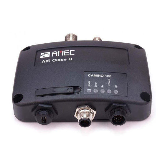
When received by other vessels and coast stations, the data built up will provide a live graphical display of traffic in the area. The CAMINO-108 has been engineered for flawless integration with navigation systems, and supports NMEA2000 and NMEA0183 communications, and its output meets IEC 62287 and related standards. - Page 9 CAMINO-108 CAMINO-108W Front Front Back Back...
-
Page 10: Equipments In The Box
Equipments in the Box Upon receiving the product please verify items in the box. If any is missing, please contact your local AMEC representative immediately. -
Page 11: External Connections
External Connections... -
Page 12: What Is Ais
What is AIS? The Automatic Identification System (AIS) is a Very High Frequency (VHF) radio broadcasting system that transfers packets of data over the VHF data link (VDL) and enables AIS equipped vessels and shore-based stations to exchange identification information and navigational data. Ships with AIS transponders continually transmit their ID, position, course, speed and other data to all nearby ships and shore stations. - Page 13 AIS Base Station: is provided by aids-to-navigation authorities to enable the ship to shore / shore to ship transmission of information. Networked AIS Base Stations can assist in providing overall maritime domain awareness. AIS AtoN (Aids to Navigation): provides an opportunity to transmit position and status of buoys and lights through the same VDL, which can then show up on AIS-ready devices within the range.
-
Page 14: Class A Vs. Class B Ais
Class A vs. Class B AIS A brief comparison of class A and class B AIS is illustrated in the following table. CAMINO-108 is a class B AIS transponder. Table 1-1 Comparison of Class A and Class B Type of AIS... -
Page 15: Ais Message Types
1.4.2 AIS Message Types Class B AIS broadcasts following message types: Static Data: MMSI Vessel name Vessel call sign Type of ship Ship dimensions / GPS antenna location Dynamic Data: Position of the vessel ... -
Page 16: Installation
Installation Installation Procedures Please familiarize the manual content before begin installation. Depending on your hardware configuration, use the following recommended steps for installation. 1) Mount the transponder unit to an appropriate location 2) Install VHF antenna 3) Install GPS antenna 4) Connect antenna cables to the transponder 5) Connect to a chartplotter via NMEA0183 or NMEA2000 interface if applicable 6) Make silent mode connection if applicable (optional external switch needed) -
Page 17: Mounting Transponder Main Unit
Mounting Transponder Main Unit The following guidelines should be noticed when selecting the environment to install your AMEC CAMINO-108: Do not install the AIS transponder in a flammable or hazardous atmosphere such as in an engine or generator room or close to fuel tanks. - Page 18 Figure 1 Mounting the transponder...
-
Page 19: Vhf/Gps Antenna Installation
VHF/GPS Antenna Installation The quality and positioning of the antenna are the most important factors dictating AIS performance. It is recommended that a VHF antenna with omnidirectional vertical polarization be specifically tuned for AIS operation band. Since the range of VHF signals is largely decided by line of sight distance, the VHF antenna should be placed as high as possible and at least 5 meters away from any constructions made of conductive materials. -
Page 20: Gps Antenna Location
GPS Antenna Location The ANT-21 GPS antenna must be installed where it has a clear view of the sky, so that it may access the horizon freely with 360° degrees, with a vertical observation of 5 to 90 degrees above the horizon as illustrated in the figure above. Enter the GPS antenna location data in “SHIP SETTING”... -
Page 21: Connecting Power And Data Cable
Connecting Power and Data Cable Connecting the CAMINO-108 to external power source and data equipments are illustrated in diagram below. (Tx Switch Box) Figure 4 Wiring instructions... - Page 22 When wiring NMEA0183 to AIS-ready equipment, please refer to your equipment manual first. CAMINO-108W supports only one configuration baud rate configuration for Tx/Rx on NMEA0183 port #2. During installation, you may have to peel off some wires to make the appropriate connections. After completing the installation, please cover all exposed wires with a rubber-vulcanized tape to prevent the devices from malfunctioning or short-circuited.
-
Page 23: Connecting With Nmea0183 Devices
Connecting with NMEA0183 Devices CAMINO-108 has two NMEA0183 ports and each NMEA 0183 port’s transmitting and receiving interface can be configured to 4800, 9600, or 38400 baud rate independently. The default baud rate for both ports is 38400-bps. Use the provided configuration utility to change baud rates. - Page 24 Data Input + (RXP) Transmit – (TXN) Output Data Input – (RXN) Note: It is not recommended to connect the Camino-108 directly to RS232 devices over NMEA1083. However, when RS232 devices are needed, please follow the instruction at www.alltekmarine.com under Camino-108´ s FAQ...
- Page 25 External CAMINO-108 NMEA0183 NMEA0183 (GPS Source) External NMEA0183 (Chartplotter) Figure 7 NMEA0183 Multiplexing Connection NMEA0183 Signal Signal Direction External NMEA0183 (CAMINO-108) Devices (CAMINO-108) Receive + (RXP) Input Data Output + (TXP) Receive – (RXN) Input Data Output - (TXN) Transmit + (TXP)
-
Page 26: Ais Silent Mode Connection
If you require Silent Mode feature, it is possible to connect an external toggle switch to CAMINO-108. Connect the toggle switch between the pink and light blue wires to enable Silent Mode function, as depicted in Figure 4. An optional external Tx Switch Box (part number SB-181) is available from AMEC to turn on/off the AIS transmission. -
Page 27: Connecting To Power Supply
Connecting to Power Supply The CAMINO-108 requires a 12V or 24V DC power supply (9.6 to 31.2V) capable of supplying 2A peak current. The red wire and the black wire on the 12 pin cable are used to connect the power supply’s positive and negative terminals. Practically, it is suggested to use the fuse panel before connecting directly to the battery/power supply. -
Page 28: Configuring Your Camino-108
It also provides the facilities to monitor and diagnose your transponder from your PC/Laptop. The AMEC AIS Configuration software can be found on the CD supplied. To install the configuration software, follow the installation instructions below. - Page 29 USB Driver Installation With the transponder power on and the USB cable attached, plug in the USB cable to the PC/Laptop. A new hardware found prompt will show up. Follow the on screen instructions and assign the correct file path of the USB driver to complete the installation.
-
Page 30: Wireless Connection (Only For Camino-108W)
3.1.2 Wireless Connection (only for CAMINO-108W) Figure 10 Wi-Fi connection for CAMINO-108W For CAMINO-108W, the connection between the Configuration Software and your transponder can also be established wirelessly. Please refer to 4.4 “Wi-Fi Configuration” about how to access CAMINO-108W from your PC as a hotspot. After your PC is wirelessly connected with the transponder, go to Option in the menu bar, then Connection, and “Wi-Fi”. - Page 31 • Ship dimensions: Enter the vessel dimensions and position of your GPS antenna installation WARNING: The MMSI number can only be entered once. Be sure to enter the correct MMSI number, as it cannot be corrected if entered incorrectly. Figure 11 Static Data Setting...
-
Page 32: Transceiver Setting
Transceiver Setting (1) To disable DSC monitoring function, select the “OFF” button. The default setting is “ON” (DSC enabled). (2) To disable the GPS output, check and select the “OFF” button. The default setting is “5 seconds” (GPS enabled). (3) GPS mode: the option “Altitude higher than 500m“ enables GPS positioning at an altitude over 500m. -
Page 33: Baud Rate Setting
Click on “BAUD RATE” tab. The default baud rate for NMEA is 38400. Enter the baud rate of connected devices. For NMEA 0183, CAMINO-108 supports baud rates 38400, 9600 and 4800. The both NMEA0183 ports of CAMINO-108 can be configured individually. For CAMINO-108W, only the first NMEA port has individual configuration. - Page 34 To read the device information, click on . A Configuration Report will pop-up in Notepad or an application that is associated for text file format. Figure 14 Configuration Report...
-
Page 35: Diagnosis Functions
Diagnosis Functions The second part of the AMEC AIS Configuration software utility features diagnosis functions. This function should be performed only after the device and antennas are all fully installed. Click on the Diagnosis tab to proceed for System Check, GPS Status, and Data Log. -
Page 36: System Check
3.5.1 System Check The System Check function can be used to check the Firmware Version, Serial Number, MMSI, GPS status, AIS TX report count, and AIS RX report count of the device. This function starts upon the connection of the device when powered on. To recheck all status, click on button. -
Page 37: Gps Status
3.5.2 GPS Status This tab shows the GPS status and the connectivities of all GPS satellites being used. Figure 17 GPS Status... -
Page 38: Data Log
3.5.3 Data Log The log shows the collected AIS data log from the device. You may save or clear the current collected log. Figure 18 Data Log... -
Page 39: Get Started
GET STARTED Start up the Transponder The transponder will start up whenever the connected power source is ON. It will operate automatically if the transponder has been properly configured using the Configuration Software and GPS/VHF antennas are also properly installed. Normally the transponder should transmit its own ship positions every 30 seconds or 3 minutes depending on the moving speed. -
Page 40: Led Indicators
LED Indicators Indicator Light Description Power Green The green LED indicates that the transponder has been powered up correctly. Error The red LED indicates that MMSI is not correctly set or the system has a BIIT error. Please refer to 4.5 for more information about BIIT. -
Page 41: Sd Card Data Logging
SD Card Data Logging The CAMINO-108 records voyage data onto a SD card in .txt format. The compatible SD card types are listed as followed: Standard “SD” with maximum 2GB size Standard “SDHC” with maximum 32GB size ... -
Page 42: W I -F I Configuration (Camino-108W Only )
Wi-Fi Configuration (CAMINO-108W only) Installation of Wi-Fi antenna is straight forward. Screw on the antenna firmly and then raise up the antenna. Figure 20 Transponder with Wi-Fi antenna connected The information below details the information required for connecting the CAMINO-108W to another device using Wi-Fi. ... -
Page 43: Built-In Integrity Test (Biit)
Built-in Integrity Test (BIIT) With BIIT (Built in Integrity Test) function, the CAMINO-108 is constantly monitoring and testing the integrity of the AIS transponder. Should an abnormal condition be detected within the device, the Error LED will alert with flashing red light. Abnormal conditions may include situations like the followings: ... -
Page 44: Ais Viewer Description
AIS Viewer Description The AIS Viewer is a complementary charting software supplied with your CAMINO-108 transponder purchase. The software installation file and its user manual can be found in the provided CD-ROM. This powerful tool allows users to display AIS targets either on a basic line map or in an alphanumeric view. -
Page 45: Introducing Amec Ais App
Introducing AMEC AIS App The AMEC AIS App is a complimentary App with the purchase of an AMEC AIS CAMINO-108W transponder. The App enables users to monitor the surrounding AIS traffics on your smart phone or tablet PC wirelessly. The AIS targets are displayed clearly in radar view or in an alphanumeric vessel list format. -
Page 46: Specifications
SPECIFICATIONS Product Specifications APPLICABLE STANDARDS IEC 62287-1 Ed. 2, 2010 IEC 61108-1 Ed. 1, 2003 IEC 61162-1 Ed. 3, 2007 IEC 60945 Ed. 4, 2002 IEC 61162-2 Ed. 1, 1998 ITU-R M.1371-4, 2010 VHF TRANSPONDER Frequency Range 156.025 MHz ~ 162.025 MHz Channel Bandwidth 25 KHz Modulation... - Page 47 GPS RECEIVER (integrated) Receiving Channels 50 channels Accuracy IEC 61108-1 compliant Output Rate 1 Hz POWER SUPPLY Supply Voltage 12V / 24V DC, 2A Power Consumption (108) Typically less than 3W average @ 12V DC Power Consumption (108W) Typically less than 4W average @ 12V DC CONNECTION INTERFACE GPS Antenna Connector TNC (Female)
- Page 48 Depth 88 mm (7.87 inch) (exclude connector) Weight 250 g SOFTWARE TOOL AMEC AIS Configuration PC configuration utility AMEC AIS Viewer AIS Viewer for PC ANT-21 GPS Antenna (optional) Cable integral 10m RG-58 cable plus mounting bracket Supply Voltage 3.3V...
-
Page 49: Dimensions
Dimensions (GPS antenna is an optional item) -
Page 50: Nmea 2000 Pgn Information
NMEA 2000 PGN Information Transmit Description 59392 ISO Acknowledgment 59904 ISO Request 60928 ISO Address Claim 126464 PGN List - Transmit PGN's group function 126996 Product Information 129025 Position Rapid Update 129026 COG SOG Rapid Update 129029 GNSS Position Data 129038 AIS Class A Position Report 129039... - Page 51 129803 AIS Interrogation 129804 AIS Assignment Mode Command 129805 AIS Data Link Management Message 129806 AIS Class A Position Report 129807 AIS Group Assignment 129808 DSC Call Information 129809 AIS Class B “CS” Static Data Report, Part A 129810 AIS Class B “CS” Static Data Report, Part B Receive Description 59392...
-
Page 52: Supported Nmea0183 Sentences
Supported NMEA0183 Sentences Transmit Sentence Description Global Positioning System Fix Data GNSS DOP and Active Satellites GNSS Satellites In View Geographic Position – Latitude/Longitude Recommended Minimum Specific GNSS Data AIS VHF Data-Link Own-Vessel Report AIS VHF Data-link Message Receive Sentence Description Datum Reference GNSS Satellite Fault Detection... -
Page 53: Troubleshooting
For AIS transmitting, GPS information from GPS antenna is required. Without GPS information, AIS will not transmit AIS signal. Please check if your GPS antenna is connected and setup correctly. CAMINO-108 receives AIS signals normally, but no one in the surrounding can see me, why? ... - Page 54 VHF antenna should be installed at mast as high as possible. The silent mode (Tx off) on CAMINO-108 is not working, why? Silent mode can be configured on CAMINO-108 by using the wires at 12-pin connector. Even though my CAMINO-108 is transmitting, why do some vessels...
- Page 55 MMSI. Please make sure that both VHF and GPS antennas and their cables are working properly and not damaged. If you still encounter difficulties to set up or operate CAMINO-108 correctly, please email to service@alltekmarine.com for further instructions.
-
Page 56: Abbreviations
ABBREVIATIONS Automatic Identification System Course Over Ground Distance to Closest Point of Approach CSTDMA Carrier-Sense Time Division Multiple Access Digital Selective Calling Electronic Chart System Estimated Time of Arrival Global Positioning System International Maritime Organization MMSI Maritime Mobile Service Identity Speed Over Ground TCPA Time to Closest Point of Approach... -
Page 57: Fcc Interference Statement
1) This device may not cause harmful interference, and 2) This device must accept any interference received, including interference that may cause undesired operation. Any changes or modifications not expressly approved by AMEC for compliance could void of the user's authority to operate the equipment. -
Page 58: Rf Exposure Warning
RF Exposure Warning WARNING: This device generates and radiates RF electromagnetic energy and must be installed and operated according to the instructions contained in this manual. Failure to do so may result in product malfunction and/or exposure to potentially harmful levels of radio frequency radiation. WARNING: Never operate this device unless it is properly connected to a VHF antenna. -
Page 59: Declaration Of Conformity
AMEC original equipment manufacturer (a ‘AMEC OEM’), the date that such vessel was purchased by the first retail customer. AMEC will, at its sole option, repair or replace any defective products or components returned during the Warranty Period in accordance with the terms, conditions and limitations set forth below. - Page 60 Other conditions This Warranty is fully transferable provided that you furnish the original proof of purchase to the AMEC -certified service agent. This Warranty is void if the seal label is removed or defaced. THE LIABILITY OF AMEC TO A CUSTOMER UNDER THIS WARRANTY, WHETHER FOR...
-
Page 61: Appendix: How To Determine Serial Port
Appendix: How to Determine Serial Port If you PC/laptop does not have available serial port, you may use a RS232-to-USB adapter. To find out the proper serial port for connection use the following instructions. Windows 7 or VISTA version: Click on “Start” Select “Control Panel” Select “Device Manager” Click Port (COM&LPT) Windows 8 and 8.1: Click (W)* + I and then click on Control Panel ... - Page 62 Alltek Marine Electronics Corporation 5F, No. 37, Ji-Hu Road, Neihu District, Taipei, 11492, Taiwan Tel: +886 2 2627 1599 Fax: +886 2 2627 1600 Email: service@alltekmarine.com Website: www.alltekmarine.com...
Need help?
Do you have a question about the Camino-108 and is the answer not in the manual?
Questions and answers