Table of Contents
Advertisement
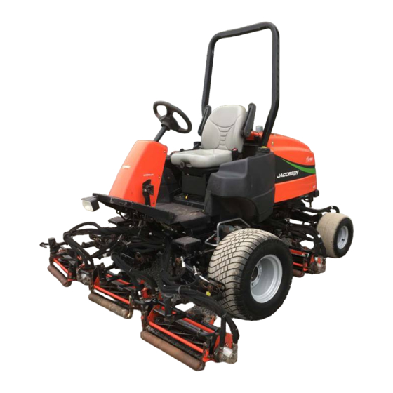
Safety, Operation, & Maintenance Manual
Super LF 1880™ Fairway Mower with ROPS
67955 – Kubota D1105-E3B, 2WD
67956 – Kubota D1105-E3B, 4WD
67957 – Kubota D1105-T-E3B, 4WD
68007 – Kubota D1105-E4B, 2WD
68008 – Kubota D1105-E4B, 4WD
WARNING
Warning: If incorrectly used, this machine can
cause severe injury. Those who use and maintain
this machine should be trained in its proper use,
warned of its dangers, and must read the entire
manual before attempting to set up, operate, adjust,
or service the machine.
GB
4160165-Rev B
Advertisement
Table of Contents

Related Manuals for Jacobsen Super LF 1880 67955


Summary of Contents for Jacobsen Super LF 1880 67955
- Page 1 4160165-Rev B Safety, Operation, & Maintenance Manual Super LF 1880™ Fairway Mower with ROPS 67955 – Kubota D1105-E3B, 2WD 67956 – Kubota D1105-E3B, 4WD 67957 – Kubota D1105-T-E3B, 4WD 68007 – Kubota D1105-E4B, 2WD 68008 – Kubota D1105-E4B, 4WD WARNING Warning: If incorrectly used, this machine can cause severe injury.
-
Page 2: Litho In U.s.a
FOREWORD This manual contains safety and operating instructions The serial plate is located on the left rear frame rail. for your new Jacobsen machine. This manual should be Jacobsen recommends you record these numbers below for easy reference. stored with the equipment for reference during operation. -
Page 3: Table Of Contents
CONTENTS ADJUSTMENTS CONTENTS General.............. 35 SAFETY Engine Belt ............35 Operating Safety ..........4 Throttle .............. 35 Important Safety Notes .........5 Neutral Switch and 4WD Cut-Out Switch ..36 SPECIFICATIONS Transport Speed ..........36 Product Identification..........6 Traction Pedal Speed Limiter ......37 Kubota D1105-E Engine ........6 Parking Brake ............ -
Page 4: Safety
(vertically), not across the face (horizontally). the job. Only use accessories and attachments approved by Jacobsen. 21. To prevent tipping or loss of control, do not start or stop suddenly on slopes. Reduce speed when making Stay alert for holes in the terrain and other hidden sharp turns. -
Page 5: Important Safety Notes
Adjustments and maintenance should always be performed by a qualified technician. If additional information or service is needed, contact your Authorized Jacobsen Dealer, who is kept informed of the latest methods to service this equipment, and can provide prompt and efficient service. Use of other than original or... -
Page 6: Specifications
SPECIFICATIONS SPECIFICATIONS PRODUCT IDENTIFICATION _________________________________________________ 67955......Super LF 1880 2WD with ROPS 67956......Super LF 1880 4WD with ROPS ® 11524 WILMAR BLVD, CHARLOTTE, NC 28273 A Textron Company 67957......Super LF 1880 Turbo 4WD with 1-800-848-1636 (US) PRODUCT OF U.S.A. ROPS 849.1 18.5... -
Page 7: Cutting Units
(457) ACCESSORIES & SUPPORT LITERATURE _____________________________________ Contact your area Jacobsen Dealer for a complete listing of accessories and attachments. CAUTION Use of other than Jacobsen authorized parts and accessories may cause personal injury or damage to the equipment. Accessories Reels Air Blow Gun ............ -
Page 8: Declaration Of Conformity
Valmistajan toiminimi ja täydellinen osoite ▪ Nom commercial et adresse complète du fabricant ▪ Firmenname und vollständige Adresse des Herstellers ▪ Jacobsen, A Textron Company Επωνυμία και ταχυδρομική διεύθυνση κατασκευαστή ▪ A gyártó üzleti neve és teljes címe ▪ Ragione sociale e indirizzo completo del fabbricante ▪... - Page 9 Plaats en datum van de verklaring ▪ Deklaratsiooni väljastamise koht ja kuupäev ▪ Vakuutuksen paikka ja päivämäärä ▪ Lieu et date de la déclaration ▪ Jacobsen, A Textron Company Ort und Datum der Erklärung ▪ Τόπος και ημερομηνία δήλωσης ▪ A nyilatkozat kelte (hely és idő) ▪ Luogo e data della dichiarazione ▪...
-
Page 10: Decals
DECALS DECALS DECALS _________________________________________________________________ Familiarize yourself with the following decals. They are critical to the safe operation of the machine. REPLACE DAMAGED DECALS IMMEDIATELY. 4181865 • Read operator's manual. Do not allow untrained • Before you clean, adjust, or repair this equipment, operators to use machine. - Page 11 DECALS Familiarize yourself with the following decals. They are critical to the safe operation of the machine. REPLACE DAMAGED DECALS IMMEDIATELY. 4181862 4181861 WARNING IMPORTANT Radiator is under pressure. Remove cap slowly to avoid personal injury. DO NOT USE STARTING ASSIST FLUIDS Use of starting assist fluids in the air intake system may be potentially explosive or cause a "runaway"...
- Page 12 DECALS 4181863 3008521 WARNING Traction Pedal To prevent cuts use socket Reverse Forward ® wrench or Turf Groomer knob to turn reel. Engaged Sound Power Level Parking Brake Disengaged 3008004...
-
Page 13: Controls Icons
CONTROLS CONTROLS ICONS ___________________________________________________________________ Hour Meter Engine Read Manual Engine Throttle Glow Plug Start High Parking Brake Coolant Fuel Cutting Units Temperature Engaged Disengaged Diesel Forward Reverse (Cut) (Backlap) Traction Pedal Mowers Lights Engine Oil Horn Pressure Forward Reverse Lower Raise Hydraulic Oil Level... - Page 14 CONTROLS Tilt Steering Lever Water Temperature Gauge B1 Parking Brake Lock Volt Meter B2 Parking Brake Release Engine Oil Pressure Light Parking Brake Pedal Horn Mow Speed Stop 2WD / 4WD Switch Traction Pedal - Forward Raise / Lower Joystick Traction Pedal - Reverse Reel Switch Seat Adjustment...
-
Page 15: Control Descriptions
CONTROLS CONTROL DESCRIPTIONS __________________________________________________ A. Tilt Steering Lever G. Seat Adjustment Pull lever up to release steering column. Tilt column Pull left side lever out to adjust seat forward or up or down to position desired. Release lever to lock backward. - Page 16 CONTROLS P. Engine Oil Pressure Light Z. Horn Switch The indicator will light if engine oil pressure drops This switch is used to test the alarm system or disable the alarm after a low oil level has been detected. Keep below 7 PSI (0.48 BAR).
-
Page 17: Operator Alerts
CONTROLS OPERATOR ALERTS _______________________________________________________ The machine monitors vital machine systems. It uses an To test alarm system: audible alarm and warning lights to alert the operator of Turn ignition switch to RUN. Engine oil light will come on for conditions requiring immediate action. When an alert one second or more. -
Page 18: Operation Daily Inspection
OPERATION OPERATION DAILY INSPECTION________________________________________________________ 2. Check the fuel supply, radiator coolant level, crankcase oil, and air cleaner indicator. All fluids CAUTION must be at the full level mark with engine cold. The daily inspection should be performed only when 3. Make sure all mowers are adjusted to the same the engine is off and all fluids are cold. -
Page 19: Operating Procedures
OPERATION OPERATING PROCEDURES _________________________________________________ WARNING A Roll Over Protection Structure (ROPS) is included with this mower. Seat belts must be worn whenever operating a mower with a ROPS. Always keep seat belt snugly adjusted. DO NOT use seat belts on a mower without a ROPS. If the mower is overturning, hold onto the steering wheel. -
Page 20: Starting
OPERATION STARTING _______________________________________________________________ IMPORTANT: Do not use starting assist fluids. Use of such fluids in the air intake system may be potentially explosive or cause a “Runaway” engine condition and could result in serious engine damage. 1. Make sure fuel shut off valve is completely open and the tow valve (See Section 6.9) is closed. -
Page 21: To Drive / Transport
OPERATION TO DRIVE / TRANSPORT ____________________________________________________ Read and follow all safety notes contained in this manual 1. Disengage all drives and raise implements to the when driving or transporting mower. Refer to Section 6.3 transport position when driving to and from the area for general operating instructions. -
Page 22: Mowing
OPERATION MOWING _________________________________________________________________ NOTICE WARNING To prevent damage to the reel and bedknife, never To prevent serious injuries, keep hands, feet, and operate reels when they are not cutting grass. clothing away from cutting unit when the blades are moving. 3. -
Page 23: Daily Maintenance
OPERATION 6.10 DAILY MAINTENANCE______________________________________________________ Important: For more detailed maintenance information, Handle fuel with care - it is highly flammable. Use an approved container; the spout must fit inside the fuel filler adjustments, and maintenance/lubrication charts, see neck. Avoid using cans and funnels to transfer fuel. the Parts &... -
Page 24: Maintenance & Lubrication Charts
MAINTENANCE & LUBRICATION CHARTS MAINTENANCE & LUBRICATION CHARTS GENERAL________________________________________________________________ 2. Lubricate with grease that meets or exceeds NLGI Grade 2 LB specifications. Apply grease with a WARNING manual grease gun and fill slowly until grease begins to seep out. Do not use compressed air guns. Before you clean, adjust, or repair this equipment, disengage all drives, lower implements to the ground, 3. -
Page 25: Maintenance Charts
- Manual grease gun with NLGI Grade 2 (Service Class LB). - Engine Oil - See Section 8.3. III - Use Jacobsen GreensCare 68 hydraulic fluid: Capacity: 8 gallons (30 Liters). Order Part No. 5003102, containing 55 gal. (208 liter) drum or Part No. 5003103 containing 5 gal. -
Page 26: Maintenance
Keep the equipment clean. ENGINE _________________________________________________________________ IMPORTANT: A separate Engine Manual, prepared by During the break-in period, Jacobsen recommends the the engine manufacturer, is supplied with this mower. following: Read the Engine Manual carefully until you are familiar During the first 50 hours of operation, a new engine with the operation and maintenance of the engine. -
Page 27: Air Filter
MAINTENANCE AIR FILTER _______________________________________________________________ Check the service indicator daily. If red band appears in the Check all hoses and air ducts. Tighten hose clamps. window (A) replace the element. Do not remove the element for inspection or cleaning. Unnecessary removal of the filter increases the risk of injecting dust and other impurities into the engine. -
Page 28: Battery
MAINTENANCE BATTERY ________________________________________________________________ Make absolutely certain the ignition switch is OFF and the When installing the battery, always assemble the Positive (RED) (+) battery cable first and the Negative key has been removed before servicing the battery. (BLACK) (-) cable last. When removing the battery, always remove the CAUTION Negative (BLACK) (-) cable first and the Positive (RED) -
Page 29: Hydraulic Hoses
Remove drain plug from bottom of main tank. Check hydraulic oil level and fill to Full mark on gauge. After oil has drained install drain plug and fill with Jacobsen GreensCare 68. Purge air from system. To prevent reels from overheating, disconnect motors from reels. -
Page 30: Electrical System
3 Not Used the problem cannot be corrected, contact an authorized 4 Ignition Relay (K17) 11 12 13 14 Jacobsen Dealer. 5 Lift Relay (K14) 6 Lift Hold Relay (K13) 7 Horn Relay (K22) Keep the wire harness and all individual wires away 8 Interlock Relay (K8) from moving parts to prevent damage. -
Page 31: Muffler And Exhaust
MAINTENANCE 8.13 MUFFLER AND EXHAUST___________________________________________________ To protect from carbon monoxide poisoning, inspect the complete exhaust system regularly and always replace a WARNING defective muffler. Exhaust fumes contain carbon monoxide that is toxic and If you notice a change in the color or sound of the exhaust, can be fatal when inhaled. -
Page 32: Care And Cleaning
Check and tighten the fan belt annually. Replace clamps and hoses every two years. If you have to add coolant more than once a month or add more than one quart at a time, have an authorized Jacobsen Dealer check the cooling system. -
Page 33: Backlapping
MAINTENANCE 8.19 BACKLAPPING____________________________________________________________ 4. Adjust the reel valves located under the operator platform, to the desired speed. WARNING 5. Apply lapping compound with a long handle brush To prevent injury, keep hands, feet, and clothing away to high spots first then along entire length of the from rotating reels. -
Page 34: Storage
MAINTENANCE 8.20 STORAGE________________________________________________________________ General Cutting Units Wash the mower thoroughly and lubricate. Repair and Wash the cutting units thoroughly, then repair and paint paint damaged or exposed metal. any damaged or exposed metal. Inspect the mower, tighten all hardware, replace worn Lubricate all fittings and friction points. -
Page 35: Adjustments
ADJUSTMENTS ADJUSTMENTS GENERAL ________________________________________________________________ adjustment cannot be made, contact an authorized Jacobsen dealer. WARNING 2. Replace, adjust, worn damaged To prevent injury, lower implements to the ground, components. disengage all drives, engage parking brake, stop 3. Long hair, jewelry, or loose fitting clothing may get engine, and remove key from ignition switch before tangled in moving parts. -
Page 36: Neutral Switch And 4Wd Cut-Out Switch
ADJUSTMENTS NEUTRAL SWITCH AND 4WD CUT-OUT SWITCH _______________________________ The traction pedal is designed to return to Neutral 2. Adjust switch (I) as required to position the sensing whenever the Forward or Reverse foot pedals are area under the return arm as shown with pump in released. -
Page 37: Traction Pedal Speed Limiter
ADJUSTMENTS TRACTION PEDAL SPEED LIMITER ___________________________________________ Cutting quality is better at speeds well below the Transport Position Mow Position transport speed of the mower. An initial mow speed of 6 mph is set at the factory and should be satisfactory for most cutting conditions. -
Page 38: Steering Adjustments
ADJUSTMENTS STEERING ADJUSTMENTS _________________________________________________ Turn wheels to straight ahead position. 2. Loosen jam nuts (Q) on both sides of tie rod (R). 3. Turn tie rod (R) to provide proper toe-in. Toe-in must not exceed +1/16 in. (1.5 mm) (S). Align ball joints and tighten jam nuts. -
Page 39: Bedknife-To-Reel
ADJUSTMENTS 9.11 BEDKNIFE-TO-REEL _______________________________________________________ (Pre-adjustment Check) Check the reel bearings for end play or radial play. There should be no end play or radial play. See Section 9.14. CAUTION To prevent personal injury and damage to the cutting edges, wear gloves and handle the reel and bedknife with extreme care. -
Page 40: Bedknife Adjustment
ADJUSTMENTS 9.12 BEDKNIFE ADJUSTMENT __________________________________________________ 1. Read Section 9.11 before making the adjustment. NOTICE 7. Start adjustment at the leading end of the reel, followed by the trailing end. The leading end of the Avoid excessive tightening or serious damage may reel blades is that end which passes over the result to bedknife and reel blades. -
Page 41: Reel Bearing
ADJUSTMENTS 9.14 REEL BEARING ___________________________________________________________ Any end play or radial play indicates bad bearings, a weak tension spring, or a backed-off nut. 1. Check bearing housing mounting hardware. Tighten or replace components as required. Carefully clean 1-27/32” threads with degreaser. (46 mm) 2. -
Page 42: Flash Attach
ADJUSTMENTS 9.18 FLASH ATTACH___________________________________________________________ Installing Cutting units Remove cap (M) on lift arm. Unfasten retaining clip (K) from pin (L) and remove pin. Place each cutting unit in front of its respective lift arm. Raise lift arm and position cutting unit so that yoke (R) is Carefully raise arm until cutting unit can be removed. -
Page 43: Torque Specification
All torque values included in these charts are approximate and are for reference only. Use of these torque values is at your sole risk. Jacobsen is not responsible for any loss, claim, or damage arising from the use of these charts. -
Page 44: Problem Solving
PROBLEM SOLVING 10.1 GENERAL PROBLEM SOLVING______________________________________________ The Problem Solving chart below lists basic problems that may occur during start-up and operation. For more detailed information regarding the hydraulic and electrical systems contact your area Jacobsen Dealer. Symptoms Possible Causes Action Engine will not start. -
Page 45: Quality Of Cut
QUALITY OF CUT QUALITY OF CUT 11.1 QUALITY OF CUT PROBLEM SOLVING________________________________________ It is recommended that a “test cut” be performed to 1. Mowing (Ground) Speed. evaluate the mower’s performance before beginning 2. Reel Bearing Condition and Pre-Load (End Play) repairs. -
Page 46: Marcelling
QUALITY OF CUT 11.3 MARCELLING_____________________________________________________________ Marcelling, like washboarding, is a cyclical pattern of varying cutting heights, resulting in a wave-like cut appearance. In most cases, the wave tip-to-tip distance is 2 in. (5 cm) or less. TN0220 NOTE: Arrow indicates direction of travel. Probable Cause Remedy Mowing (ground) speed is too fast. -
Page 47: Step Cutting
QUALITY OF CUT 11.4 STEP CUTTING____________________________________________________________ Step cutting occurs when grass is cut taller on one side of a reel than the other or one cutting unit to another. This is usually caused by mechanical wear or an incorrect roller or HOC (height-of-cut) adjustment. -
Page 48: Scalping
QUALITY OF CUT 11.5 SCALPING _______________________________________________________________ Scalping is a condition in which areas of grass are cut noticeably shorter than the surrounding areas, resulting in a light green or even brown patch. This is usually caused by an excessively low height-of-cut (HOC) setting and/or uneven turf. -
Page 49: Stragglers
QUALITY OF CUT 11.6 STRAGGLERS ____________________________________________________________ Stragglers are scattered blades of uncut or poorly cut grass. TN0223 NOTE: Arrow indicates direction of travel. Probable Cause Remedy Bedknife improperly adjusted. Adjust reel-to-bedknife setting. Dull reel or bedknife cutting edges. Sharpen or replace reel blade and bedknife as necessary. Mowing (ground) speed is too fast. -
Page 50: Streaks
QUALITY OF CUT 11.7 STREAKS ________________________________________________________________ A streak is a line of uncut grass. This is usually caused by a nicked or bent bedknife. TN0224 NOTE: Arrow indicates direction of travel. Probable Cause Remedy Damaged bedknife. Replace bedknife. Damaged or unevenly worn reel. Inspect reel. -
Page 51: Windrowing
QUALITY OF CUT 11.8 WINDROWING ____________________________________________________________ Windrowing is the deposit of clippings concentrated at one end of cutting unit(s) or between two cutting units, forming a line in the direction of travel. TN0225 NOTE: Arrow indicates direction of travel. Probable Cause Remedy Grass is too tall. -
Page 52: Rifling Or Tramlining
QUALITY OF CUT 11.9 RIFLING OR TRAMLINING __________________________________________________ Rifling or tramlining is a pattern of varying cutting heights, resulting in a wave-like cut appearance, usually due to heavy contact points across a reel and/or bedknife. NOTE: Arrow indicates direction of travel. Probable Cause Remedy Reel and/or bedknife unevenly worn. -
Page 53: Notes
NOTES NOTES... - Page 54 Equipment from Jacobsen is built to exacting standards ensured by ISO 9001 and ISO 14001 registration at all of our manufacturing locations. A worldwide dealer network and factory trained technicians backed by Genuine Jacobsen Parts provide reliable, high-quality product support.
Need help?
Do you have a question about the Super LF 1880 67955 and is the answer not in the manual?
Questions and answers
The alternator is not charging the battery