Table of Contents
Advertisement
Quick Links
Advertisement
Table of Contents
Troubleshooting

Related Manuals for RuggON VM-521

Summary of Contents for RuggON VM-521
- Page 1 VM-521 User's Manual...
-
Page 3: Table Of Contents
Table of Contents About this Manual Related Information ..................1 Conventions ....................1 Basic Safety Guidelines Intended Use ....................2 Maintenance and Operation Overview ............2 Safety ......................2 Electrical Hazards ..................2 Safety Guidelines for Mounting ..............3 Environmental ....................4 Radio Transmissions ..................4 Cleaning and Servicing .................4 Regulatory and Certification .................5 Lithium Battery Safety Statement ..............6 Chapter 1. - Page 4 Chapter 5. Operation Powering the Device ...................53 Defrost/Defog Option ..................54 Calibrating the Touch Screen ..............56 Protective Film ....................58 VM-521 Configuration Options ..............58 Chapter 6. Troubleshooting Troubleshooting the Wi-Fi Connection ............60 Troubleshooting 802.1x Security ..............61 Troubleshooting Device Operations ............61 Call Product Support ..................62...
- Page 5 Chapter 7. Maintenance Cleaning the Device ...................63 Returning the Device ..................63 Contacting RuggON ...................63 Appendix A. Technical Specifications Port Pin Assignments .................64...
-
Page 6: About This Manual
About this Manual The VM-521 User’s Manual provides instruction for qualified personnel to follow when setting up a new VM-521 device. This document is intended for use by qualified personnel to compliment the training and expertise, not to replace it. -
Page 7: Basic Safety Guidelines
The VM-521 is designed and manufactured according to strict controls and following the stated safety regulations. The following list identifies incorrect operating uses of the VM-521. Incorrect use of the VM-521 can lead to hardware damage, safety issues and possible risk to personnel health: „... -
Page 8: Safety Guidelines For Mounting
The device may fall during transportation or installation and cause injury. It is recommended to have at least two people when installing/uninstalling the device. When the mounting bracket breaks When installing the VM-521, be aware of the sudden breaks of the bracket which may cause „ injury. -
Page 9: Environmental
The operator is solely responsible for this type of operation. Installation Distance To follow the limits set by the FCC for exposure to radio waves, install the VM-521 with the minimum distance (20cm) between individuals and the PC antenna . -
Page 10: Regulatory And Certification
Regulatory and Certification This equipment has been tested and found to comply with the limits for a Class B digital device, pursuant to Part 15 of the FCC Rules. These limits are designed to provide reasonable protection against harmful interference in a residential installation. This equipment generates, uses, and can radiate radio frequency energy and, if not installed and used in accordance with the instructions, may cause harmful interference to radio communications. -
Page 11: Lithium Battery Safety Statement
European Notice CE Declaration of Conformity For the following equipment: tablet with built-in 802.11a/b/g/n WLAN module Is herewith confirmed to comply with the requirements set out in the Council Directive on the Approximation of the Laws of the Member States relating to Electromagnetic Compatibility (2004/105/ EC), Low-voltage Directive (2006/95/EC), the procedures given in European Council Directive 1999/5/EC. -
Page 12: Chapter 1. Introduction
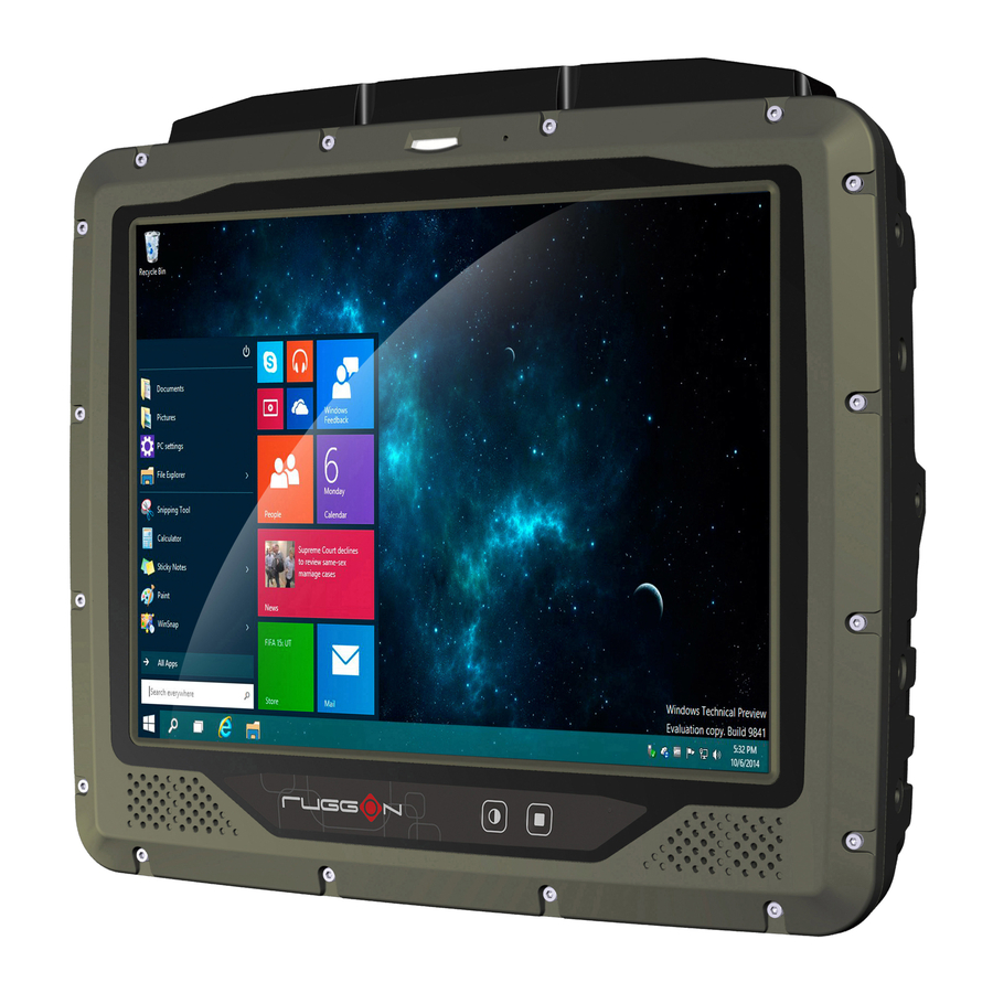
The device is equipped with 802.11, Bluetooth, GPS or GLONASS for wireless data communications. The VM-521 is a rugged 10.4” tablet computer capable of 1024 x 768 resolution. The anti- reflection tempered 5-wire resistive touch panel is capable of sunlit and hyper dimming for day and night mode readability. - Page 13 Introduction Item Description 24/48V nominal Voltage range: 18V - 60V DC Power Pack Galvanically isolated 24/48V Maximum output: 35W 35W Nominal Withstands bursts up to 2 kV DC/DC Delay Timer/Filter Battery 2,900mAh, 7.5V Housing (Mechanical) Die-cast aluminum alloy, fanless design Dual Gigabit LAN for teaming / redundant function support „...
-
Page 14: Unpacking The Device
Certification CE, FCC, CB Unpacking the Device Before you begin the installation or configuration process make sure to inspect all components and accessories. Contact your representative if there are any missing or damaged items. See “Contacting RuggON” on page 63. -
Page 15: Scope Of Delivery
Introduction Scope of Delivery The VM-521 is delivered with the following items. The VM-521 is not shipped with accessories. All accessories are sold separately. For help, contact your local RuggON sales representative. See “Contacting RuggON” on page 63. Please verify the delivery of the contents upon receipt. -
Page 16: Identifying The Device
Introduction Identifying the Device Device Overview Figure 1. Front View Table 2. Front View Item Description LED indicator See “LED Status” on page 55. Side view See “Side View” on page 14 for further information. Back of device. See “Rear View” on page 15 for further Rear view information. -
Page 17: Front View
Introduction Front View Figure 2. Front View 5 4 3 Table 3. Front View Item Description LED indicator See “LED Status” on page 55. Speakers 2 x 2W waterproof, front mounted speakers. Defrost/defog key Key provides function for panel defrost and defog (optional function). FN key Key provides function for Home or SW initiation (programmable). -
Page 18: Bottom View
Power switch Turns the VM-521 on or off. COM1 Connect RS-232 devices such as a printer or scanner to the VM-521. Connect CANBUS cables to allow devices to communicate within a CANBUS x 2 vehicle without the use of a host computer. -
Page 19: Side View
Introduction Side View Figure 4. Side View Left View Right View Table 5. Side View Item Description Communication Open to access SD and SIM ports. cover Mounting holes Securing holes for additional mounting options. -
Page 20: Rear View
Introduction Rear View Figure 5. Rear View Table 6. Rear View Item Description WWAN1 Connect WWAN1 antenna. WLAN1 Connect WLAN1 antenna. Connect GPS antenna. WLAN2 Connect WLAN2 antenna. WWAN2 Connect WWAN2 antenna. Communication Open to access SD and SIM ports. cover Service cover Remove to service SSD, DIMM, video card or WWAN card. -
Page 21: Dimensions
Introduction Dimensions The following section provides information regarding the dimensions of the device. The dimensions are in centimeters and inches, respectively. Figure 6. Front View Dimensions 27.60 cm / 10.87” 22.27 cm / 8.77” Figure 7. Side View Dimensions... -
Page 22: Touch Screen
Introduction Figure 8. Rear View Dimensions WWAN 1 WLAN 1 WWAN 2 WLAN 2 7.00 cm / 2.76” 10.00 cm / 3.94” Touch Screen Always use the point of the stylus for tapping or making strokes on the touch screen. Never use an actual pen, pencil, or sharp/abrasive object on the touch screen. -
Page 23: Chapter 2. Getting Started
Connecting a USB Cable Connect the DB9 to dual USB type cable to the VM-521. Plug the desired devices, such as a USB mouse or storage device. USB devices may be installed, removed or swapped without power down the VM-521. -
Page 24: Using Ethernet Cabling
Getting Started Using Ethernet Cabling To prevent damage to the device, connect all cabling and accessories before powering up the device. Connecting Ethernet Cabling A shielded cable is required to maintain emissions and device compliance. Connect to a local area network (LAN) using an RJ45 (Ethernet) cable. Locate the LAN 1 or 2 port on the bottom of the device. -
Page 25: Using Com Cabling
Getting Started Using COM Cabling To prevent damage to the device, connect all cabling and accessories before powering up the device. Connecting RS-232 Cable Connect a peripheral device, such as a printer or other device with a serial port. Locate the COM 1 port on the bottom of the device. Connect the RS-232 cable to the designated port. -
Page 26: Using Canbus Cabling
Getting Started Using CANBUS Cabling To prevent damage to the device, connect all cabling and accessories before powering up the device. Connecting a CANBUS Cable CANBUS ports allow the devices to communicate with each other within a vehicle without a host computer. -
Page 27: Using Dio Cabling
Getting Started Using DIO Cabling To prevent damage to the device, connect all cabling and accessories before powering up the device. Connecting a DIO Cable The DIO port supports 4 input and 4 output ports. Locate the DIO port on the bottom of the device. Connect the DIO cable to the port. -
Page 28: Using Audio Cabling
Connecting an Audio Cable The VM-521 is equipped with audio jacks to connect to headphones or microphone. The connectors are color coded and marked Audio Out and Audio In. The audio ports require a 3.5mm audio cable to connect to the device. -
Page 29: Connecting To Power Supply
Getting Started Connecting to Power Supply The VM-521 is equipped with a galvanically seperated, integrated DC power supply. Power is connected on the underside of the device using a bare leads power cord. The power switch is also located on the underside of the device. - Page 30 Getting Started Twist the nut as shown in the following image to lock the power cord to the device. Figure 17. Locking the Power Cord Connect the other end of the power cord to the power supply source. Secure the cable using wire ties or other applicable materials. Removing the Power Adapter Locate the DC In port and connected power cord on the bottom of the device.
- Page 31 Getting Started Remove the power cord from the device to disconnect it. Figure 19. Removing the Power Cord...
-
Page 32: Chapter 3. Hardware Installation
Hardware Installation Chapter 3. Hardware Installation This section provides information for the installation and removal of supported components. Only qualified personnel are authorized to service or install hardware. Installing or removing components should only be performed on a clean, well-lit work surface. When necessary, protect the work surface, the device, and components from electrostatic discharge. - Page 33 Hardware Installation Grasp one end of the service cover and angle it up to remove. Figure 21. Removing the Service Cover Replacing the Service Cover Power down the device and disconnect from all the power source. Unmount the device from the mounting apparatus. Place the device display side down on a clean work surface.
-
Page 34: Dimm Module
Hardware Installation Secure the service cover in the VM-521 with the provided screws. Figure 23. Securing the Screws DIMM Module Prevention of EMI interference in this device is not guaranteed if the original components are replaced. A single DIMM module slot is available for memory expansion. The device supports up to 8GB of SO-DIMM DDR3L SDRAM. -
Page 35: Removing A Dimm Module
Hardware Installation Remove the DIMM module from its packaging. Take care not to touch the connectors on the module. Handle the DIMM module by the edges. Do not touch the connectors to prevent damage to the modules. Insert the DIMM module into the slot making sure the protrusion on the slot is aligned with the indentation on the module. - Page 36 Hardware Installation Pull the locking levers to unlock the DIMM. Figure 26. Releasing the Locking Levers Remove the DIMM from the connector. Figure 27. Removing a DIMM Module Replace the service cover. See “Replacing the Service Cover” on page 28.
-
Page 37: Ssd Module
Unmount the device from the mounting apparatus. Place the device display side down on a clean work surface. Remove the service cover. See “Removing the Service Cover” on page 27. Locate the SSD connector on the VM-521. Figure 28. Rear View: Locating the SSD Connector MAIN SSD Connector Remove the SSD module from its packaging. - Page 38 Hardware Installation 11. Connect the SSD to the SATA cable. Figure 30. Connecting the SATA cable to an SSD Module 12. Hold the SSD module with one hand. With the other hand push in the SATA cabling underneath the chassis. It is necessary to tuck the cables in to allow for enough space to install the SSD module.
- Page 39 Hardware Installation Removing an SSD Module Power down the device and disconnect from all power sources. Unmount the device from the mounting apparatus. Place the device display side down on a clean work surface. Open the service cover. See “Removing the Service Cover” on page 27. It may be necessary to grasp the silicone guard strip and gently pull them up to remove the SSD module from the bay.
-
Page 40: Pcie Expansion Options
Hardware Installation Remove the silicone guard strips from the SSD module. Do not throw them away the guard strips away. Keep the guard strips for later use on the replacement SSD module. Figure 34. Removing the SSD Silicone Guard Strips Replace the service cover. - Page 41 Figure 36. Installing a mini PCIe Card 11. Secure the mini PCIe card to the VM-521 with the provided screws. Figure 37. Securing the Screws 12. Connect the mini PCIe cabling to the mini PCIe card.
- Page 42 Remove the SSD module. See “Removing an SSD Module” on page 34. Disconnect mini PCIe cabling from the mini PCIe card. Remove the screws securing the mini PCIe card to the VM-521. Figure 38. Removing the Screws Disconnect the mini PCIe card from the VM-521.
- Page 43 Open the service cover. See “Removing the Service Cover” on page 27. Remove the SSD module and place it on a clean surface. See “Removing an SSD Module” on page 34. Locate the WWAN card on the VM-521. Figure 40. Rear View: Locating the WWAN Card Main...
-
Page 44: Removing The Wwan Card
The holes on the card must line up with the holes in the screw posts. Figure 41. Installing the WWAN Card 10. Secure the WWAN card to the VM-521 with screws. Figure 42. Securing the Screws 11. Connect antennas cables to the following connectors: main to blue labeled connector, GPS to red labeled connector and AUX to black labeled connector. - Page 45 Remove the SSD, see “Removing an SSD Module” on page 34. Disconnect antenna cabling from the WWAN card. Remove the screws securing the WWAN card and the VM-521. Figure 43. Removing the Screws Disconnect the WWAN card from the VM-521.
- Page 46 Hardware Installation Removing the Communications Cover The communications bay is located on the left rear side of the device. For further information see “Device Overview” on page 11. Power down the device and disconnect from all the power source. Unmount the device from the mounting apparatus. Place the device display side down on a clean work surface.
- Page 47 Hardware Installation Open the cover as shown in the following image. Figure 47. Removing the Communications Cover Once the communications cover is removed, you can install or remove the following items: „ Mini SIM card SD card „ Replacing the Communications Cover The communications bay is located on the left rear side of the device.
- Page 48 Gently press it in place to seat it properly. If installed correctly, there should be no gaps between the cover and the chassis. Figure 49. Inserting the Communications Cover Secure the communications cover and the VM-521 with screws. Figure 50. Securing the Screws Return the device to the mounting apparatus and install.
- Page 49 Hardware Installation Installing a mini SIM Card The device includes a mini SIM card slot for cellular and wireless connection. Only a mini SIM card is supported in the slot. Check with your network or cellular service provider for availability and cost rates. Power down the device and disconnect from all the power source.
- Page 50 Hardware Installation Removing a mini SIM Card Power down the device and disconnect from all power sources. Unmount the device from the mounting apparatus. Place the device display side down on a clean work surface. Remove the communications cover. See “Removing the Communications Cover” on page Press the mini SIM card in and release it.
-
Page 51: Installing An Sd Card
Hardware Installation Installing an SD Card The device supports different types of memory cards for easier data storage. The supported types for SD cards are as follows: SD card „ SDHC card „ „ Mini-SD card (with adapter) Power down the device and disconnect from all power sources. Unmount the device from the mounting apparatus. -
Page 52: Removing The Sd Card
Hardware Installation Removing the SD Card Power down the device and disconnect from all the power source. Unmount the device from the mounting apparatus. Place the device display side down on a clean work surface. Locate the communications cover and remove it. See “Removing the Communications Cover”... -
Page 53: Installing Antennas
Ensure that the installation surface is grounded by connecting grounding straps between the surface and the vehicle chassis. Ensure that the antenna cable can be easily routed to the VM-521. Route the antenna cable as far away as possible from any vehicle electronic units and its associated wiring. - Page 54 Connecting a WLAN Radio Antenna The WLAN antenna for the VM-521 mobile workstation is an optional component available through your representative. For WLAN connector locations see “Installing Antennas” on page 48. An external WLAN antenna jack is located on the rear of the device. To connect an external antenna, the connector end of the antenna must be RP SMA male to fit into the RP SMA female jack on the device.
-
Page 55: Chapter 4. Hardware Mounting
„ Device Enclosure The VM-521 supports the installation of various wall and wall mounting brackets. The following illustrations displays the screw locations for the supported installation types. To prevent any damage or injury, make sure the mounting bracket is securely attached. -
Page 56: Device Cooling
VESA 75 Mounting Option VESA 75 mounting option, M5 thread The VM-521 supports a standard VESA version MIS-D, 75, C (75 mm distance quadrate order, M5 thread, deepness 7.5 mm) through the four drill holes (See 1 in “Figure 56. Rear View, dimensions in centimeters and inches”... -
Page 57: Power Supply
„ Connect the VM-521’s as close to the battery as possible. Malfunctions may occur if the the VM-521 is conected to large electrical loads, such as converters for the forklift motor may result in random restarts. -
Page 58: Chapter 5. Operation
Starting Up the Device Only power up the VM-521 after connecting all of the cables. The VM-521 is powered up by connecting it to an appropriate power supply and then using the Power switch. The VM-521 must be connected to an SELV circuit. Make sure there is a suitable disconnecting device such as a power switch or circuit breaker in the power supply circuit. -
Page 59: Defrost/Defog Option
Operation Defrost/Defog Option The touch screen is available with a defrost and defog function for users who use the device in extreme temperature environments. The function is optional and only available upon request. Enabling Defrost Function Figure 59. Defrost Function Defrost/Defog In extreme cold conditions (moving into a cold environment), press the button to enable the... -
Page 60: Led Status
Operation Brightness and Dimming Control Figure 61. Brightness and Dimming Function Brightness and Dimming Defrost/Defog LED Status Table 8. LED Status Color Description None Hyper dimming mode or shut down. Green Normal. Battery mode. Adjust the illumination of the display to setup optimal conditions in Sunlight or Nigh mode operations. -
Page 61: Calibrating The Touch Screen
Operation Calibrating the Touch Screen The touch screens of all VM-521 devices that come delivered with an operating system (Windows or Linux) are already calibrated. You may need to calibrate your screen if you tap on one area and it registers in a different area of the screen. - Page 62 Operation Tap and hold until the display shows OK. Figure 64. Calibration Screen Continue to follow the instructions until the process is finished. Once calibration is achieved a prompt displays. Tap OK to complete the calibrate process. Figure 65. Complete Calibrate...
-
Page 63: Protective Film
Operation Protective Film The front display of the VM-521 is protected during transport by the use of a transparent film. This film should remain on the front display during assembly to avoid damage to the front display surface. Only remove the film after all of the assembly work has been completed. -
Page 64: Speaker Volume
Press FN Key > press or tap Control Panel > Bluetooth Devices „ Restart/Shutdown Use the Windows interface to restart or shut down the VM-521. To restart: Press FN Key > press or tap Start > arrow next to Shut down > Restart „... -
Page 65: Chapter 6. Troubleshooting
If you send the computer in for service, it is the user’s responsibility to save any data, settings, and configuration. RuggON is only responsible for hardware when repairing or replacing the device. -
Page 66: Troubleshooting 802.1X Security
Troubleshooting Troubleshooting 802.1x Security Use the following table to troubleshoot problems with your 802.1x security that will prevent you from connecting to your network, such as an incorrect password. The computer indicates it is not authenticated. Make sure that: The User Name and Password parameters on the computer must match the user name „... -
Page 67: Call Product Support
If you are using security, know the type and the full set of parameters „ If you are using RuggON Terminal Emulator, know the version and protocol. If you are not „ using RuggON Terminal Emulator, know the language your custom application was written in and the tools you used to create it. -
Page 68: Cleaning The Device
Maintenance Chapter 7. Maintenance Cleaning the Device Danger to electric shock when cleaning or maintaining the VM-521. To avoid electric shock, turn the VM-521 off and disconnect it from the power supply before cleaning or maintaining it. Housing „ The housing of the VM-521 is best cleaned with a damp cloth. -
Page 69: Port Pin Assignments
Technical Specifications Appendix A. Technical Specifications Port Pin Assignments Use this section as a reference for the pin assignments of the various ports available on the VM-521. DIO Port Figure 67. DIO Port Pin Assignment Table 9. DIO Port Pin Assignments... - Page 70 Technical Specifications RS-232 Port By default, pin 9 is configured to provide +5V for an external bar code scanner, or it can be configured to provide RI. Figure 68. RS-232 Port Pin Assignment Table 10. RS-232 Port Pin Assignments Signal Description Data carrier detect (input) Receive data (input)
- Page 71 Technical Specifications CANBUS Ports Figure 70. CANBUS Ports Pin Assignment Table 12. CANBUS Ports Pin Assignments Signal Description No connected CAN_L CAN_L bus line dominant low 5V level Ground No connected No connected No connected CAN_H CAN_H bus line dominant high 5V level No connected No connected...
-
Page 72: Expansion Port
Technical Specifications Expansion Port Figure 71. EXPANSION Port Pin Assignment Table 13. EXPANSION Port Pin Assignments Signal Description CH1: Audio Left Audio left input CH2: Video Video input CH2: Audio Right Audio right input No connected CH3: Audio Right Audio right input CH1: Video Video CH1: Audio Right... -
Page 73: Usb Port
Technical Specifications USB Port Figure 72. USB Port Pin Assignment Table 14. USB Port Pin Assignments Signal USB2_D- USB2_D+ USB1_D+ USB1_D- USB2_PWR USB1_PWR Not used Power Connector If you are connecting to an external DC/DC supply, you must apply power to DC+. If you are connecting to 10 to 60V vehicle power, connect power to V In+.
Need help?
Do you have a question about the VM-521 and is the answer not in the manual?
Questions and answers