Table of Contents
Advertisement
Advertisement
Table of Contents

Subscribe to Our Youtube Channel
Summary of Contents for ddrum DDTi
- Page 1 REFERENCE MANUAL...
-
Page 3: Table Of Contents
RETURN TO DEFAULT VALUE ........18 FACTORY RESET ............. 18 MIDI SYSEX TRANSFERS ..........18 DEFAULT SETTINGS FOR THE DDTi ......19 OTHER APPLICATIONS OF THE DDTi ........ 20 DDTi KIT PRESETS ............... 21 DDTi DEFAULT GLOBAL PARAMETERS ......22 TROUBLESHOOTING ............ -
Page 5: Introduction
With the Ddrum DDTi, you can connect your favorite acoustic drum triggers or electronic percussion pads and control sounds on external drum machines, modules or software devices. Here at Ddrum, we take pride in building electronic instruments and controllers for the modern musician. The DDTi allows you to explore new avenues of sonic possibilities with an intuitive percussion interface. -
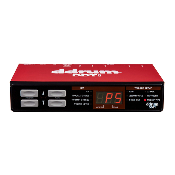
Page 6: Front Panel Overview
(USB), the unit will draw power from the USB connection to your computer. USB Port – The USB port is used to transmit MIDI data between the DDTi and a computer. This port may also be used to power the unit if the power button is in the OUT position (USB). However, if your computer’s USB port does not provide sufficient power to the DDTi, please use the included AC... -
Page 7: Hookup Diagram
Before turning on the DDTi, connect all triggers, pads, footswitches, MIDI devices and external modules as shown above. If you would like to use the DDTi with a computer, connect a USB cord from the DDTi to your computer’s USB port. -
Page 8: Computer Installation
USB device. How to connect and use the DDTi with a software application: Connect a USB cord from the USB port of the DDTi to the USB port of your computer. When the DDTi is connected to a computer using a USB cord, the computer’s USB bus will provide power to the unit. - Page 9 Please make sure that your soundcard’s latency (or buffer) is set to a low number so when you hit the pads on the DDTi, your computer will output the sound promptly. Latency and buffering is usually adjusted in your software’s Preferences menu.
-
Page 10: Getting Started - Using Kits
The DDTi automatically goes into Kit selection function when it is turned on. Notice that the LED next to Kit is lit. If you are in a different function, you can always get to the Kit selection function by using the function up/down buttons. -
Page 11: Program Change Messages
This means that, effectively, you can have each kit on the DDTi address a different set of sounds in your DAW or external MIDI device. By default, each kit on the DDTi is set to “---“. A Program Change message of “---“ means that no Program Change message will be sent when the kit is loaded. -
Page 12: Editing Kits
EDITING KITS Editing kits is a powerful tool for customizing your DDTi. When you are editing a kit, the information displayed on the screen will always reflect the parameters of the last trigger in the current kit that was hit. To modify the parameters of a certain trigger, just strike it –... -
Page 13: Trigger Midi Note
MIDI Note Numbers, depending on the position of the pedal. When you press the pedal down and engage the hi-hat input, the DDTi will output a closed hi-hat note. With the pedal released, engaging the hi-hat input will output an open hi-hat note. -
Page 14: Setting Global Parameters
The global parameters include Gain, Velocity Curve, Threshold, Crosstalk, Retrigger and Trigger Type. Please take some time to optimize the DDTi for use with your preferred trigger devices. Once you begin tweaking the trigger parameters, you will notice that the LED next to Kit will begin blinking, alerting you that changes have been made to the existing configuration. -
Page 15: Gain
GAIN The Gain parameter describes how a trigger will react when it is engaged. With a high gain setting, you don’t have to engage the trigger very hard to achieve a maximum velocity output. On the other hand, with a low gain setting it is harder to achieve a maximum velocity output when engaging the trigger hard. -
Page 16: Velocity Curve
VELOCITY CURVE A Velocity Curve describes how a trigger’s velocity varies with the force applied. This is a useful feature when trying to customize how a trigger responds to your playing style. Different Velocity Curves will have different input/output ratios associated with them and will cause a different response, so take some time to get familiar with how the Velocity Curve setting corresponds to the way you like to play. -
Page 17: Threshold
THRESHOLD False triggering occurs when a trigger is engaged accidentally, often due to stage vibrations. The Threshold setting can help prevent false triggering. High Threshold values will require you to hit the pad harder to register a note. Threshold should be set based on your playing style so please try different Threshold settings until you find one that works best for you. -
Page 18: X-Talk (Crosstalk)
You may also wish to use the X-Talk function as well. The X-Talk feature describes the degree to which the DDTi will attempt to reject crosstalk. Positive X-Talk values attempt to intelligently suppress crosstalk. If a very loud and a very soft trigger arrive almost simultaneously, the X-Talk function will assume that the soft trigger is crosstalk and will suppress it from sounding. -
Page 19: Retrigger
Retrigger setting is 100ms, the DDTi will ignore the second sound and only output the first. On the other hand, if the Retrigger setting is set to 25ms, the DDTi will output both sounds, since the second sound occurs beyond the Retrigger boundary. -
Page 20: Trigger Type
TRIGGER TYPE You can select the type of trigger you are using in the Trigger Type function. There are many different types of triggers available on the market today – too many to cover individually in this manual – but most triggers can be grouped into the categories outlined below. -
Page 21: Using Hi-Hat Pedals
If a hi-hat pedal is selected, you will see “CAL” displayed on the screen. You can adjust the calibration manually or you can let the DDTi adjust it automatically by leaving the pedal in the up position and pressing up value and down value buttons simultaneously. -
Page 22: Sending Messages
This will transfer all the presets from the DDTi to your SysEx application. To transfer data to the DDTi, please make sure that the DDTi is connected via USB to your SysEx application. Then, simply play the SysEx data you would like to transfer to the DDTi. -
Page 23: Default Settings For The Ddti
NOTE # 49 *When using a hi-hat foot pedal connected to the Hi-hat footswitch input on the DDTi, the Hi-hat input will alternate between sending MIDI Note # 44 and MIDI Note # 42, depending on the position of the Hi-hat footswitch. -
Page 24: Other Applications Of The Ddti
OTHER APPLICATIONS OF THE DDTi The DDTi can be used for a variety of applications which use MIDI as their control protocol. For example, the DDTi can be used to trigger melodic sounds on sound modules or VST instruments. This means that you can play pitched instruments, such as vibraphones, marimbas, xylophone, even a piano or a violin, straight from the DDTi. -
Page 25: Ddti Kit Presets
DDTi KIT PRESETS KIT#0 – BFD LITE INPUT CHANNEL MIDI NOTE # ZONE CHANNEL RING MIDI NOTE # HI HAT FOOT SWITCH – CHANNEL 10, MIDI NOTE # 44 (INPUT3) CLOSED HI HAT NOTE # 42 KIT#1 – GM DRUMS... -
Page 26: Ddti Default Global Parameters
MIDI NOTE # HI HAT FOOT SWITCH – CHANNEL 1, MIDI NOTE # 35 (INPUT3) CLOSED HI HAT NOTE # 42 DDTi DEFAULT GLOBAL PARAMETERS The following are the factory default global parameters for the DDTi: INPUTS 1-10 HI HAT INPUT GAIN... -
Page 27: Troubleshooting
The display does not light No power. If you are using USB power, check that the power switch on the back of the DDTi is in the OUT (USB) position. If you are using an AC adapter, check that the adapter is plugged into a live power outlet and that the power switch is in the IN (AC) position. - Page 28 Please refer to “Setting Global Pad triggers when Gain, X-Talk and Threshold Parameters” section to fine tune the DDTi. another pad is hit. not set correctly. There is too much There is another device on Try unplugging USB devices (especially your computer’s USB bus.
- Page 29 DDTi probably needs to be calibrated to match the output of your particular pedal. Perform the calibration procedure described in the "X-Talk"...
-
Page 30: Midi Implementation
MIDI IMPLEMENTATION Function Transmitted Recognized Remarks Basic Default 1-16 Memorized Channel Changed 1-16 Adjustable by user per pad Note Number: 0-127 Note On 1-127 Velocity Note Off After Touch Pitch Bend Control Ctrl # 4 0-127 Foot Pedal CC message Change Ctrl # 64 0-127... - Page 32 MANUAL REVISION C...
- Page 33 www.ddrum.com...
Need help?
Do you have a question about the DDTi and is the answer not in the manual?
Questions and answers