
Related Manuals for connexx SBS-32Z4


Summary of Contents for connexx SBS-32Z4
- Page 1 MODEL:SBS-32Z4 OPT FM --INSTALLATION AND OPERATION MANUAL-- PLEASE READ INSTRUCTIONS CAREFULLY AND KEEP FOR FUTURE REFERENCE...
-
Page 2: Table Of Contents
TABLE OF CONTENTS INTRODUCTION....................1 FEATURES......................1 PACKING LIST....................1 IMPORTANT SAFETY INSTRUCTIONS............2-3 PLACING AND MOUNTING................4 GENERAL VIEW....................5 SPEAKER/POWER WIRE SOCKET DIAGRAM..........6 REMOTE CONTROL..................7 BATTERY INSTALLATION--REMOTE CONTROL..........8 GENERAL OPERATIONS.................. 9 LISTEN TO FM RADIO..................10 BLUETOOTH PAIRING AND PLAYBACK............10 ADDING OPTIONAL EXTERNAL SUBWOOFER..........11 CONNECT USING OPTICAL................12 CONNECT TO TV/DVD..................13 AUX IN.......................14... -
Page 3: Introduction
INTRODUCTION Thank you for choosing a Connexx product. We hope you will find the Instructions in this owner's manual clear and easy to follow. If you take a few minutes to review, you will learn how to use all of the features of your new soundbar stereo for maximum enjoyment. -
Page 4: Important Safety Instructions
The lighting flash with arrowhead symbol within an CAUTION equilateral triangle is intended to alert the user to RISK OF ELECTRIC SHOCK the presence of uninsulated “dangerous voltage” DO NOT OPEN within the product’s enclosure that may be of sufficient magnitude to constitute a risk of electric CAUTION: TO REDUCE THE RISK OF shock to persons. - Page 5 6 ) Clean only with dry cloth 13 ) Refer all servicing to qualified service Unplug this product from the wall outlet before personnel. Servicing is required when the cleaning. Do not use liquid cleaners or aerosol apparatus has been damaged in any way, such as power-supply cord or plug is damaged, liquid cleaners.
-
Page 6: Placing And Mounting
PLACING AND MOUNTING 1. Placing on the table When placing the Sound Bar on an entertainment center, bookshelf, or any type of enclosed space, be sure to allow space around the Sound Bar for ventilation. If the Sound Bar is enclosed in a tight space, without ventilation, heat generated from the Sound Bar could pr oduce a potential heat hazard. -
Page 7: General View
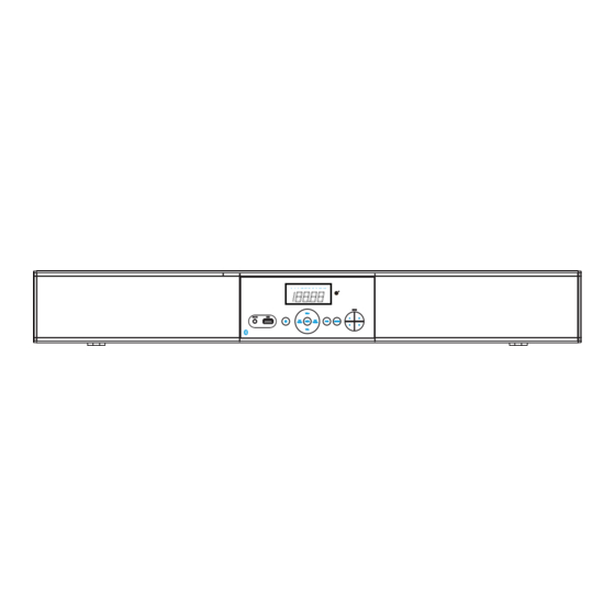
GENERAL VIEW Front View OPT FM 5 6 7 8 9 1. LED Display 5. PREVIOUS/TUNE Down 9. Volume Up 6. Volume Down 10. PAIR Button 2. AUX IN Jack Play/Pause/ Preset/ 11. SOURCE Button 3. USB Jack 12. Remote Sensor Memory/Preset Play Button 13. -
Page 8: Speaker/Power Wire Socket Diagram
SPEAKER/POWER WIRE SOCKET DIAGRAM 10A FUSE SPEAKER (6X4-ohms) WIRING COLOR CODE GUIDE 12V DC CAUTION! Power Connecting the speakers Extension incorrectly will cause distortion and damage the power amplifier. RED - POWER IN 12V + BLACK - POWER GND 10A FUSE GREEN/BLACK - C LEFT - RED - POWER IN 12V + 10A FUSE... -
Page 9: Remote Control
REMOTE CONTROL POWER OPTICAL ZONE A ZONE B AUX IN ZONE C ZONE D / / TUN+ TUN- VOL- VOL+ / PAIR MUTE 1. POWER button 10. ZONE A button 2. Bluetooth Mode Switch button 11. ZONE B button 3. AUX IN Mode Switch button 12. -
Page 10: Battery Installation--Remote Control
BATTERY INSTALLATION--- REMOTE CONTROL Battery Installation 1.Slide and lift the battery door (Figure 1). 2.Install 2 (two) AAA size batteries into the battery compartment as indicated by the polarity markings (Figure 2). 3.Replace the battery door (Figure 3). Battery Precaution Remote Control Effective Range When there is an obstacle between the unit and the remote control, the remote control may not operate properly. -
Page 11: General Operations
GENERAL OPERATIONS 1. Press the Power button on the unit or remote control to power on the unit from standby mode. 2. The default mode is "FM". Press the SOURCE button repeatedly to switch to desired mode. Follows the order below: OPT FM 3. -
Page 12: Listen To Fm Radio
BT Device. ) Notes: When the external BT Device searched the unit, will appear on the "SBS-32Z4" display of the external BT Device. Pairing code "0000" may need to be entered. Normal operation after paired: Normal operation after paired: --Press the VOL (Volume)-/+ buttons to adjust volume level as desired. -
Page 13: Adding Optional External Subwoofer
ADDING OPTIONAL EXTERNAL SUBWOOFER 10A FUSE NOTE: Before connecting, disconnect power. There is a SPEAKER SELECTOR on the back of the unit to turn on or turn off the internal subwoofer output or external subwoofer output. IN(Internal subwoofer)-- When the switch is moved to "IN" position, there will be no audio output from the external subwoofer. -
Page 14: Connect Using Optical
CONNECT USING OPTICAL 10A FUSE Optical Cable(Not Supplied) DVD or TV NOTE: Before connecting, disconnect power. 1. Connect one end of optical connection cable ( not supplied ) to the optical jack on the rear of the unit as pictured above. 2. -
Page 15: Connect To Tv/Dvd
CONNECT TO TV/DVD 10A FUSE MAIN TV White Yellow Yellow Yellow Yellow TV 4 TV 3 TV 2 DVD or TV NOTE: Before connecting, disconnect power. NOTE: Before connecting, disconnect power. 1. Connect as the figure above.(TV 2, 3, 4 are optional to connect) 2. -
Page 16: Aux In
AUX IN : LISTEN TO EXTERNAL AUDIO DEVICES 1. Connect one end of audio connection cable (not supplied) to the AUX IN jack on the front of the unit as pictured above. 2. Connect the other end to the Audio out/Line out/Phone jack on the external player ( such as iPod, iPhone, iPad, MP3 player, Discman... -
Page 17: Troubleshooting Guide
TROUBLESHOOTING GUIDE Check the following guide before requesting service Check the following guide before requesting service No power power cable not connected ~Check fuse or blown fuse ~Check 12V connection Raise volume level by pressing the VOL Volume in minimum position (Volume) + button Play the music/movie in the connected No sound... -
Page 18: Specifications
SPECIFICATIONS Operation Voltage......................DC10V-14V Power Supply Requirement..............DC 12 Volts, Negative Ground Overall Dimension..................813(W)x107.2(H)x83(D)mm Device and Accessories Net Weight................2.2kg(4.85 lb) Max Power Consumption......................90W Video In/Out Level................1 Vp-p/Load impedance:75 ohm Radio Coverage ....................FM 87.5 -108.0 MH Bluetooth Effective Range.....................Up to 30 feet (Measured in open area. Wall and structures may affect the effective range.) Remote Effective Range....................Up to 15 feet Specifications subject to change without notice. - Page 19 www.riverparkinc.com 2014 RIVERPARK Inc. V. 050514...
Need help?
Do you have a question about the SBS-32Z4 and is the answer not in the manual?
Questions and answers
Where is the 10 AMP fuse, there is power but the LED display is no showing. Unit only shows blue power light