Table of Contents
Advertisement
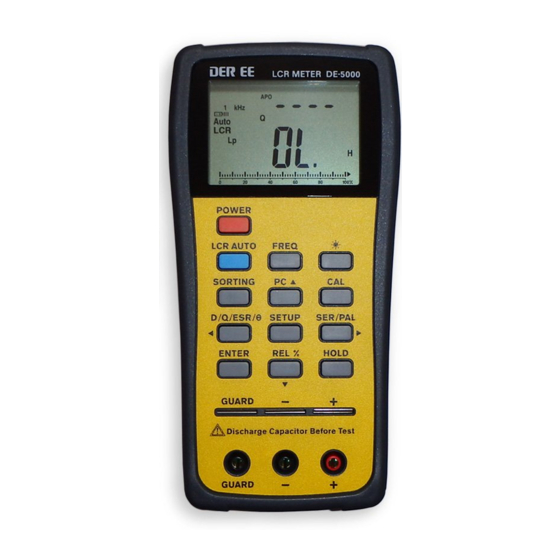
INSTRUCTION MANUAL
DUAL DISPLAY L C R METER
Model : DE-5000
Thank you for purchasing our products. Please read this
instruction manual before using the meter and keep it
properly for contingent use.
Table of Contents
I.
Introduction...............................................
II.
Measuring Principle Introduction............
III. Panel Illustration......................................... 08 ~ 10
IV. LCD Display Illustration............................. 11 ~ 12
V.
Operation Instructions............................... 13 ~ 34
1. Power ON/OFF ...................................... 13 ~ 14
2. CAL .................................................... 15 ~ 17
3. LCR AUTO ............................................ 18 ~ 20
Measurement........................................
5. FREQ .................................................. 22 ~ 23
6. Backlight ..............................................
7. SORTING / SETUP / ENTER .................... 23 ~ 25
8. PC ......................................................
9. D/Q/ESR/ ............................................ 27 ~ 28
10. SER/PAL ..............................................
11. REL .................................................... 30 ~ 31
12. HOLD ...................................................
VI. Replacing Batteries...................................
VII. General Specification................................
VIII. Electrical Specification.............................. 35 ~36
- 1 -
03
04 ~ 07
20 ~ 21
23
26
29
32
33
34
Advertisement
Table of Contents

Summary of Contents for DEREE DE-5000
-
Page 1: Table Of Contents
DUAL DISPLAY L C R METER Measuring Principle Introduction………… 04 ~ 07 III. Panel Illustration………........ 08 ~ 10 Model : DE-5000 IV. LCD Display Illustration………………..……… 11 ~ 12 Operation Instructions………………..……….. 13 ~ 34 Thank you for purchasing our products. Please read this 1. -
Page 2: Introduction
I. Introduction Electrical Symbol Risk of Danger. Important information. This LCR Meter is a 19999/ 9999 counts dual display, high See Manual. accuracy LCR meter, which could measure Inductance/ Capacitance/ Resistance with secondary parameters including AC/DC power adaptor input polarity dissipation factor (D), quality factor (Q), phase angle ( ), equivalent series/ parallel resistance (ESR or Rp). -
Page 3: Measuring Principle Introduction
> 0, the reactance is inductive. In other words, if < 0, the II. Measuring Principle Introduction reactance is capacitive. There are two types for reactance. The one is the inductive reactance XL and the other is the capacitive reactance XC. Impedance parameter introduction XL = 2 f L XC =1/ (2 f C) - Page 4 There are two factors to provide the ratio of real part and is defined as total impedance measured to DUT imaginary part. Usually the quality factor Q is used for ( device under test ) by the special test fixture which has some inductance measurement and the dissipation factor D is used parasitic impedance.
-
Page 5: Panel Illustration
Alligator Panel Illustration Test Lead Case tweezers (optional) Rear Guard Line Front panel Side “GUARD” provides shield for DUT ( device under test ), improvised test leads or equipments situated at places where with high interference. IR to USB case (optional) - 8 - - 9 -... -
Page 6: Lcd Display Illustration
III. LCD Display Illustration LCD display POWER To power on/off the instrument LCR auto mode, Inductance, LCR AUTO Capacitance, Resistance and DC resistance measurement selection key FREQ Testing frequency selection key Backlight display SORTING Sorting mode control key UART output control Open/Short calibration mode D/Q/ ESR/ D/Q/ ESR/ parameters selection key... -
Page 7: Operation Instructions
Dissipation factor, Quality factor or Phase angle is IV. Operation Instructions D/Q/ active for L/C measurement mode To access optimum precision for all L, C and R measurements AC Resistance in parallel mode is active especially at the highest and the lowest ranges, please use the Open/Short calibration mode alligator test leads (TL-21) or improvised test leads applying to the HOLD... -
Page 8: Cal
2. CAL This function enables the LCR meter’s internal parameters and external connector residues to be calibrated to have better and precise measurements. To make better precision measurements on extremely high or low impedance ranges of L,C,R, it is highly recommended that do OPEN/SHORT calibration to reduce the parasitic effect of the test fixture before measuring. - Page 9 If calibration is completed, PASS or FAIL appears on the primary display. Enter short calibration mode. If both calibrations are passed, press ”CAL” key again to * Short alligator test leads. store the calibration value to EEPROM.(Electrically Erasable Programmable Read-Only Memory). Press “...
-
Page 10: Lcr Auto
3. LCR AUTO The “LCR AUTO” key selects the primary parameter Enter Auto R mode measurement function. Each press of the key will select either Auto-LCR mode, Auto-L mode, Auto-C mode, Auto-R mode or Auto-DCR mode Press “LCR AUTO ” key The default setting is LCR Auto mode which can check the type of Impedance smartly and enter to the measurement... -
Page 11: Inductance / Capacitance / Resistance Measurement
If C < 5pF. The parameter on sub-display is Rp. *2: When LCR Auto mode is active, the secondary parameter will show c. To measure SMD component by SMD tweezers (TL-22, the equivalent resistance in parallel mode (Rp) to replace the D option). -
Page 12: Freq
5. FREQ The “FREQ” key selects the testing frequency. Each press of The test frequency is 120Hz. the key will select either 1kHz, 10 kHz, 100kHz, 100Hz or 120Hz, total 5 frequency for selection. The default frequency setting is 1kHz. Press “FREQ ”... - Page 13 The primary display will show PASS or FAIL which based on whether the impedance measured exceeds tolerance range. Last digit will flash The secondary display will show the measurement reading. Press “ ” key to select the desired digit. When sorting mode is active, operate “ SETUP ” key along with Press “...
-
Page 14: D/Q/Esr
8. PC D/Q/ESR/ IR to USB case (IR to USB case is optionel. Measuring In LCR Auto mode, this key has no function data can be transferred to PC with it. ) USB socket The “D/Q/ESR/ ”key selects the secondary parameter Snap on IR to USB case and connect measurement function. -
Page 15: Ser/Pal
10. SER/PAL In LCR Auto mode, this key has no function. Secondary display parameter Press the “SER/PAL” key to select parallel or series mode,. When any one of primary parameter measurement function is selected, parallel or series mode will be selected automatically based on the total equivalent impedance measured. -
Page 16: Rel
11. REL Remove the current DUT ( device under test ) and insert In LCR Auto mode, this key has no function. another one Press the “REL” key to enter relative mode. The value on the The new reading is shown on the display will be stored as reference value and “... -
Page 17: Hold
12. HOLD V. Replacing Batteries Press the “HOLD” key to freeze the reading on the primary display and “HOLD” will appear. The meter is powered by a single 9V battery, with NEDA1604 , JIS006P and IEC6F22 carbon-zinc or alkaline battery. Alkaline In the Hold mode, only key and PC key have function. -
Page 18: General Specification
VII. Electrical Specification VI. General Specification Accuracy: ±(% of reading + number of least significant digits) at 23°C ± 5°C, <75% R.H. Item Dual Display L C R Meter Specifications are based on measurement performed at input sockets or terminals with Alligator Test Lead Case (TL-21) after short &... - Page 19 * Do open/short calibration before measuring for above ranges with * to have better precision measurements. conforms to ISO standards. If any further inquiry needed, Accuracy v.s. Resistance (Z please visit our website at www.deree.com.tw 100/120Hz 1kHz 10kHz 100kHz 0.1~1...
Need help?
Do you have a question about the DE-5000 and is the answer not in the manual?
Questions and answers