Table of Contents
Advertisement
NM70I-847/NM70I-807/NM70I-1007U/NM70I-1037U Setup Manual
FCC Information and Copyright
This equipment has been tested and found to comply with the limits of a Class B
digital device, pursuant to Part 15 of the FCC Rules. These limits are designed
to provide reasonable protection against harmful interference in a residential
installation. This equipment generates, uses, and can radiate radio frequency
energy and, if not installed and used in accordance with the instructions, may
cause harmful interference to radio communications. There is no guarantee that
interference will not occur in a particular installation.
The vendor makes no representations or warranties with respect to the contents
here and specially disclaims any implied warranties of merchantability or fitness
for any purpose. Further the vendor reserves the right to revise this publication
and to make changes to the contents here without obligation to notify any party
beforehand.
Duplication of this publication, in part or in whole, is not allowed without first
obtaining the vendor's approval in writing.
The content of this user's manual is subject to be changed without notice and we
will not be responsible for any mistakes found in this user's manual. All the brand
and product names are trademarks of their respective companies.
Dichiarazione di conformità
sintetica
Ai sensi dell'art. 2 comma 3 del D.M.
275 del 30/10/2002
Si dichiara che questo prodotto è
conforme alle normative vigenti e
soddisfa i requisiti essenziali richiesti
dalle direttive
2004/108/CE, 2006/95/CE e
1999/05/CE
quando ad esso applicabili
Short Declaration of conformity
We declare this product is complying
with the laws in force and meeting all
the essential requirements as specified
by the directives
2004/108/CE, 2006/95/CE and
1999/05/CE
whenever these laws may be applied
Advertisement
Table of Contents

Related Manuals for Biostar NM70I-847


Summary of Contents for Biostar NM70I-847
- Page 1 NM70I-847/NM70I-807/NM70I-1007U/NM70I-1037U Setup Manual FCC Information and Copyright This equipment has been tested and found to comply with the limits of a Class B digital device, pursuant to Part 15 of the FCC Rules. These limits are designed to provide reasonable protection against harmful interference in a residential installation.
-
Page 2: Table Of Contents
Table of Contents Chapter 1: Introduction.......... 1 Before You Start ................1 Package Checklist ................1 Motherboard Specifications .............2 Central Processing Unit (CPU) ............3 Rear Panel Connectors..............3 Motherboard Layout................4 Chapter 2: Hardware Installation ......5 Connect Cooling Fans..............5 Install System Memory ..............6 Expansion Slots.................7 Jumper Setting ..................8 Headers &... -
Page 3: Chapter 1: Introduction
NM70I-847/NM70I-807/NM70I-1007U/NM70I-1037U CHAPTER 1: INTRODUCTION 1.1 Before You Start Thank you for choosing our product. Before you start installing the motherboard, please make sure you follow the instructions below: Prepare a dry and stable working environment with sufficient lighting. Always disconnect the computer from power outlet before operation. -
Page 4: Motherboard Specifications
1x S/PDIF out Connector Form Factor mini-ITX Form Factor, 170 mm x 170 mm Windows XP / Vista / 7 / 8 OS Support Biostar reserves the right to add or remove support for any OS with or without notice. -
Page 5: Central Processing Unit (Cpu)
NM70I-847/NM70I-807/NM70I-1007U/NM70I-1037U 1.4 Central Processing Unit (CPU) The motherboard is equipped with an onboard Intel processor and a CPU cooler. Model: Onboard Intel CPU: NM70I-847 Intel® Celeron® Processor 847 (Dual Core 1.1GHz, Sandy Bridge) NM70I-807 Intel® Celeron® Processor 807 (Single Core 1.5GHz, Sandy Bridge) NM70I-1007U Intel®... -
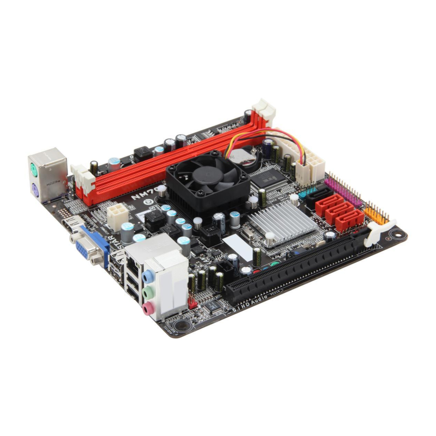
Page 6: Motherboard Layout
Motherboard Manual 1.6 Motherboard Layout Note: ■ represents the 1 pin. -
Page 7: Chapter 2: Hardware Installation
NM70I-847/NM70I-807/NM70I-1007U/NM70I-1037U CHAPTER 2: HARDWARE INSTALLATION 2.1 Connect Cooling Fans These fan headers support cooling-fans built in the computer. The fan cable and connector may be different according to the fan manufacturer. Connect the fan cable to the connector while matching the black wire to pin#1. -
Page 8: Install System Memory
Motherboard Manual 2.2 Install System Memory A. DDR3 Modules Step 1: Unlock a DIMM slot by pressing the retaining clips outward. Align a DIMM on the slot such that the notch on the DIMM matches the break on the slot. Step 2: Insert the DIMM vertically and firmly into the slot until the retaining chip snap back in place and the DIMM is properly seated. -
Page 9: Expansion Slots
NM70I-847/NM70I-807/NM70I-1007U/NM70I-1037U C. Dual Channel Memory Installation Please refer to the following requirements to activate Dual Channel function: Install memory module of the same density in pairs, shown in the table. Dual Channel Status DDR3_A1 DDR3_B1 Disabled Disabled Enabled (O means memory installed, X means memory not installed.) Note: The DRAM bus width of the memory module must be the same (x8 or x16) 2.3 Expansion Slots... -
Page 10: Jumper Setting
Motherboard Manual 2.4 Jumper Setting The illustration shows how to set up jumpers. When the jumper cap is placed on pins, the jumper is “close”, if not, that means the jumper is “open”. Pin opened Pin closed Pin1-2 closed JCMOS1: Clear CMOS Header Placing the jumper on pin2-3, it allows user to restore the BIOS safe setting and the CMOS data. -
Page 11: Headers & Connectors
NM70I-847/NM70I-807/NM70I-1007U/NM70I-1037U 2.5 Headers & Connectors ATXPWR1: ATX Power Source Connector This connector allows user to connect 24-pin power connector on the ATX power supply. Assignment Assignment +3.3V +3.3V -12V +3.3V Ground Ground PS_ON Ground Ground Ground Ground Ground PW_OK Standby Voltage+5V... - Page 12 Motherboard Manual PANEL1: Front Panel Header This 16-pin connector includes Power-on, Reset, HDD LED, Power LED, and speaker connection. It allows user to connect the PC case’s front panel switch functions. Assignment Function Assignment Function Speaker Connector Speaker Power LED (+) HDD LED (+) Power LED (+) Power LED...
- Page 13 NM70I-847/NM70I-807/NM70I-1007U/NM70I-1037U F_USB1/F_USB2: Headers for USB 2.0 Ports at Front Panel This header allows user to connect additional USB cable on the PC front panel, and also can be connected with a wide range of simultaneously accessible external Plug and Play peripherals.
- Page 14 Motherboard Manual JSPDIFOUT1: Digital Audio-out Connector The JSPDIFOUT1 is for connecting the PCI bracket SPDIF output. Assignment SPDIF_OUT Ground J_COM1: Serial Port Connector The motherboard has a Serial Port Connector for connecting RS-232 Port. Assignment Carrier detect Received data Transmitted data Data terminal ready Signal ground Data set ready...
- Page 15 NM70I-847/NM70I-807/NM70I-1007U/NM70I-1037U J_PRINT1: Printer Port Connector This header allows you to connector printer on the PC. Assignment Assignment -Strobe Ground -ALF Data 6 Data 0 Ground -Error Data 7 Data 1 Ground -Init -ACK Data 2 Ground -Scltin Busy Data 3...
-
Page 16: Chapter 3: Uefi Bios & Software
CD-ROM, or from the file location on the Web. BIOSTAR BIOS Flasher BIOSTAR BIOS Flasher is a BIOS flashing utility providing you an easy and simple way to update your BIOS via USB pen drive. Note1: This utility only allows storage device with FAT32/16 format and single partition. - Page 17 NM70I-847/NM70I-807/NM70I-1007U/NM70I-1037U 6. Select the proper BIOS file, and a message asking if you are sure to flash the BIOS file. Click Yes to start updating BIOS. 7. A dialog pops out after BIOS flash is completed, asking you to restart the system.
- Page 18 Reset to restart the computer. Then, the BIOS Update is completed. BIOS Update Utility (through a BIOS file) 1. Installing BIOS Update Utility from the DVD Driver. 2. Download the proper BIOS from http://www.biostar.com.tw/ 3. Launch BIOS Update Utility and click the Update BIOS button on the main screen.
- Page 19 NM70I-847/NM70I-807/NM70I-1007U/NM70I-1037U 4. A warning message will show up to request your agreement to start the BIOS update. Click OK to start the update procedure. 5. Choose the location for your BIOS file in the system. Please select the proper BIOS file, and then click on Open.
-
Page 20: Software
Motherboard Manual 3.3 Software Installing Software Insert the Setup DVD to the optical drive. The driver installation program would appear if the Autorun function has been enabled. Select Software Installation, and then click on the respective software title. Follow the on-screen instructions to complete the installation. Note1: All the information and content about following software are subject to be changed without notice. - Page 21 NM70I-847/NM70I-807/NM70I-1007U/NM70I-1037U After filling up this information, click “Send” to send the mail out. A warning dialog would appear asking for your confirmation; click “Send” to confirm or “Do Not Send” to cancel. If you want to save this information to a .txt file, click “Save As…” and then you will see a saving dialog appears asking you to enter file name.
- Page 22 Motherboard Manual BIOScreen Utility This utility allows you to personalize your boot logo easily. You can choose BMP as your boot logo so as to customize your computer. Please follow the step-by-step instructions below to update boot logo: Load Image:Choose the picture as the boot logo. Transform:Transform the picture for BIOS and preview the result.
-
Page 23: Rapid Start Technology
NM70I-847/NM70I-807/NM70I-1007U/NM70I-1037U Rapid Start Technology Intel® Rapid Start technology enables your system to get up and running faster from even the deepest sleep, saving time and power consumption. Feel secure knowing that your system will still resume to working conditions in the event of unexpected power loss while in sleep mode. - Page 24 Motherboard Manual 3-3 After rebooting, the system will setup Intel® Rapid Start Technology automatically. We recommend you restart the system after this installation is complete, Step 4: Configuring Intel® Rapid Start Application Launch the Intel® Rapid Start Technology Manager application from [Start] > [All Programs] >...
-
Page 25: Chapter 4: Useful Help
NM70I-847/NM70I-807/NM70I-1007U/NM70I-1037U CHAPTER 4: USEFUL HELP 4.1 Driver Installation After you installed your operating system, please insert the Fully Setup Driver DVD into your optical drive and install the driver for better system performance. You will see the following window after you insert the DVD The setup guide will auto detect your motherboard and operating system. -
Page 26: Extra Information
Motherboard Manual 4.2 Extra Information CPU Overheated If the system shutdown automatically after power on system for seconds, that means the CPU protection function has been activated. When the CPU is over heated, the motherboard will shutdown automatically to avoid a damage of the CPU, and the system may not power on again. -
Page 27: Ami Bios Beep Code
NM70I-847/NM70I-807/NM70I-1007U/NM70I-1037U 4.3 AMI BIOS Beep Code Boot Block Beep Codes Number of Beeps Description Continuing Memory sizing error or Memory module not found POST BIOS Beep Codes Number of Beeps Description Success booting. Display memory error (system video adapter) 4.4 Troubleshooting... -
Page 28: Appendix: Spec In Other Languages
Motherboard Manual APPENDIX: SPEC IN OTHER LANGUAGES Arabic اﻟﻤﻮاﺻﻔﺎت NM70I-847: Intel® Celeron® Processor 847 (Dual Core 1.1GHz) NM70I-807: Intel® Celeron® Processor 807 (Single Core 1.5GHz) ﻗﺎﻋﺪة وﺣﺪة اﻟﻤﻌﺎﻟﺠﺔ NM70I-1007U: Intel® Celeron® Processor 1007U (Dual Core 1.5 GHz) اﻟﻤﺮآﺰﻳﺔ NM70I-1037U: Intel® Celeron® Processor 1037U (Dual Core 1.8 GHz) Intel NM70 ﻣﺠﻤﻮﻋﺔ... -
Page 29: French
1x Connecteur sortie S/PDIF Facteur Facteur d'encombrement mini-ITX, 170 mm x 170 mm d'encombrement Windows XP / Vista / 7 / 8 Support SE Biostar se réserve le droit d’ajouter ou d'enlever le support pour toute SE avec ou sans préavis. -
Page 30: German
1x Header für Druckerport 1x Serieller Port-Header 1x S/PDI-Auswurfsverbindung Formfaktor mini-ITX Formfaktor, 170 mm x 170 mm Windows XP / Vista / 7 / 8 OS-Unterstützung Biostar reserves the right to add or remove support for any OS with or without notice. -
Page 31: Italian
Fattore di Forma Fattore di Forma mini-ITX, 170 mm x 170 mm Windows XP / Vista / 7 / 8 Supporto SO Biostar si riserva il diritto di aggiungere o ritirare il supporto per qualsiasi SO con o senza preavviso... -
Page 32: Japanese
Motherboard Manual Japanese 仕様 NM70I-847: Intel® Celeron® Processor 847 (Dual Core 1.1GHz) NM70I-807: Intel® Celeron® Processor 807 (Single Core 1.5GHz) CPU サポート NM70I-1007U: Intel® Celeron® Processor 1007U (Dual Core 1.5 GHz) NM70I-1037U: Intel® Celeron® Processor 1037U (Dual Core 1.8 GHz) INTEL NM70 チップセット... -
Page 33: Polish
Port szeregowy x1 Port zewnętrzny S/PDIF x1 Obudowa Obudowa mini-ITX, 170 mm x 170 mm Windows XP / Vista / 7 / 8 Obsługa OS Biostar zastrzega sobie prawo do dodania lub wycofania obsługi dla OS, z wypowiedzeniem lub bez wypowiedzenia. -
Page 34: Portuguese
Conector Externo S/PDIF x1 Fator de Fôrma Fator de Fôrma mini-ITX, 170 mm x 170 mm Windows XP / Vista / 7 / 8 Suporte OS Biostar reserva seu direito de adicionar ou retirar o suporte para qualquer OS com ou sem notificação. -
Page 35: Russian
1 контакт последовательного порта 1 соединитель S/PDIF-Out Конструктив Форм-фактор mini-ITX, 170 мм x 170 мм Windows XP / Vista / 7 / 8 Поддержка ОС Biostar оставляет за собой право добавлять или удалять поддержку любой ОС, с уведомлением или без. -
Page 36: Spanish
Factor de Forma Factor de Forma mini-ITX, 170 mm x 170 mm Windows XP / Vista / 7 / 8 Soporte OS Biostar reserva su derecho de añadir o retirar el soporte para cada OS con o sin notificación. 2013/06/21...
Need help?
Do you have a question about the NM70I-847 and is the answer not in the manual?
Questions and answers