Advertisement
Table of Contents
Safety Precautions ...........................2
Installation............... .......................3
Power Supply .................................4
Set -up .........................................4
Advance Settings ............................5
Servicing. .....................................10
Cleaning and Maintenance ...............21
Troubleshooting..............................21
QR Codes .....................................24
Spare Parts List..............................25
Plumbing diagram ..........................27
Wiring diagram ..............................28
Prior authorization must be obtained from
GMCW for all warranty claims.
GRINDMASTER ®
BY GMCW ™
© GMCW, 2013
Printed in Thailand
ENGLISH
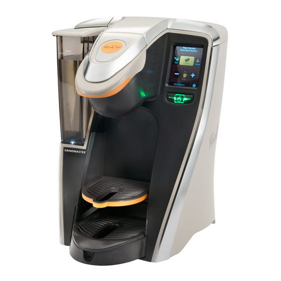
Single Cup Brewer
Service Manual
Model RC400
MODEL: RC400
GMCW
4003 Collins Lane
Louisville, KY 40245 USA
(502) 425-4776
(800) 695-4500 (USA & Canada only)
FAX (502) 425-4664
www.gmcw.com
1213 Form # BW-306-01
Part # 390-00021
Advertisement
Table of Contents

Related Manuals for RealCup RC400

Summary of Contents for RealCup RC400
-
Page 1: Table Of Contents
Single Cup Brewer Service Manual Model RC400 Table of Contents Safety Precautions ……………………...2 Installation…………... …………………..3 Power Supply ……..…………………….4 Set –up …………….…………………….4 Advance Settings …….………………...5 Servicing. ……………………………….10 Cleaning and Maintenance …………...21 Troubleshooting………………………...21 QR Codes ……..………………………..24 Spare Parts List..……………………….25 Plumbing diagram ……………………..27 Wiring diagram …………………………28... -
Page 2: Safety Precautions
Safety Precautions Important Safety Information This is the safety alert symbol. It is used to alert you to potential personal injury hazards. Obey all safety messages that follow this symbol to avoid possible injury or death. For your safety and the safety of others, read all warnings and the operator’s manual before installing or using the product. -
Page 3: Installation
NOTICE For best results, remove used Real Cup™ capsule from brew chamber when brewing is complete. Avoid spills by not removing the reservoir while Auto-Fill unit is filling; allow complete filling cycle before removing reservoir. A qualified professional should perform installation, maintenance and repairs. Installation, maintenance or repairs by unqualified personnel may damage the brewer and void the manufacturer’s ... -
Page 4: Power Supply
Installation (continued) Power Supply WARNING Disconnect power if the machine functions abnormally and notify qualified service personnel for repairs. Do not permit non-qualified service personnel to attempt repairs. No user serviceable components inside the brewer. Do not disassemble brewer. Notice This appliance is equipped with a three wire power cord. -
Page 5: Advance Settings
Note: Auto-Fill ONLY: The water is supplied directly to the unit and the water fill level marking is not used. Operation is not affected by the water being below the fill line. Fill Level Advance Settings: The advance setting feature is available to authorized service agents only. It allows changes beyond the skills of the regular end user. - Page 6 Setting a new passcode: Select “Set Passcode” This selection takes you back to the basic settings screen. Re-Enter new Passcode Enter new Passcode NOTE: Factory Default beverage is COFFEE Changing Beverage Type: Depicts selected beverages. Note that if you had unselected “Ice To set default beverage, select the Tea”...
- Page 7 Changing Beverage Size: Select or deselect a size to enable/ disable Select a size to set as default size. The selection will remain highlighted to indicate it being the default. NOTE: Factory default size is 8 oz Changing Brew Count: Changing Water Temperature: Press “+”...
- Page 8 Edit Service Contact A series of screens (with different characters that may be required) will allow you to change Service Contact information. There are two lines for name and address and one line for phone number. By selecting this icon, you switch from upper case to lower case.
- Page 9 Edit Service Contact Name (continued): Once you are in the number screen, if you press this symbol, Once you are in the char- you will go to the acter screen, if you press character screen. this symbol, you will go to the English characters screen.
-
Page 10: Servicing
Adjusting Brew Volumes: This option will allow you to change Brew Volumes factory default as much as ten percent. You will be able to go up ten percent or down ten percent. Example: For 10 oz, if you adjust to +10, it will set the vol- ume to 11 oz. - Page 11 Servicing (continued): 3) Replacing flip down Grid assembly. To replace the grid sub-assembly, follow the steps as outlined below with the use of a small flat head screwdriver. 4) Replacing reservoir components. To replace reservoir components, first remove reservoir from brewer. Follow the steps as outlined below. ENGLISH...
- Page 12 Servicing (continued): Warning The next section covers instructions for replacing internal components in the brewer. Always unplug machine before servicing any internal parts. 5) Servicing internal brewer components. In order to service any of the components in the following section, you will first have to gain access to the interior of the brewer.
- Page 13 Servicing (continued): 5a) Servicing check valve or 3-way valve. These two components are located on the upper rear section of the brewer. To replace the check valve: 1. Cut strain relief straps using wire cutters. 2. Pull inner and outer tubes away from check valve using needle nose pliers. Follow the sequence in reverse when replacing.
- Page 14 Servicing (continued): 5b) Servicing air pump and relief valve. These two components are located on the upper rear section of the brewer, to the left of the 3-way valve when viewed from rear. To replace the air pump: 1. Cut the strain relief on the top of the air pump. 2.
- Page 15 Servicing (continued): 5c) Servicing flow meter and water pump. These two components are located on the lower left area of the brewer when viewed from rear. To replace the flow meter: 1. Disconnect wire connector on the top of the flow meter. 2.
- Page 16 Servicing (continued): 5d) Servicing Bezel and Capsule Holder. These two components are located in the brew chamber. To replace the Bezel. Pull on one of the rear corners and pull part away from the lip of the carrier. To replace, line up the slot on the bezel with the lip of the carrier, rotate, and snap into position.
- Page 17 Servicing (continued): The sketch below shows the bypass kit on the probe holder assembly. To service by pass on probe holder assembly: Pull the Manifold Fitting away from the probe holder. Remove the bypass parts. Replace the spring, ring, and ball as shown. Please make sure that the spring is sitting properly inside of the manifold fitting.
- Page 18 5g) Access to the electronics module: a) Loosen the upper screw (pointing to 1) and pull the clamp up. This will allow you to remove the clamp and the electronic housing. b) Remove the four screws on the back of the electronics module. This will give you access to all the components in this module.
- Page 19 Servicing (continued): 6) Servicing the water inlet valve, the USB board, and the power cord. In order to gain access to these parts, you will have to follow the sequence below: 6a) Servicing the water inlet valve, the USB board, and the power cord. Follow the sequence outlined below to gain access to these components.
- Page 20 Servicing (continued): 6b) Servicing the Triac assembly and the Transformer Follow the sequence outlined below to gain access to these components. Reverse order for reassembly. 6c) Servicing the Tank Assembly Follow the sequence outlined below to gain access to the Tank Assembly. Cut the strain relief straps on the upper and lower hoses, pull hoses from tank, and disconnect all wiring.
-
Page 21: Cleaning And Maintenance
Cleaning and Maintenance WARNING Brew probes are sharp. To prevent injury, do not place fingers inside the brew chamber. To reduce foreign material from entering the brewer, keep brew chamber and reservoir lids closed. Cleaning: NOTE: When cleaning the unit, do not use cleansers, liquid bleach, powders, or any other substance that contains chlorine. - Page 22 Troubleshooting (continued): PROBLEM SOLUTION No power Verify unit is plugged to a 120V/15 amp rated outlet and power switch in the ON position. Time to fill longer than expected 1. Make sure water is turned on. 2. Make sure water pressure is above 20 PSI 3.
- Page 23 PROBLEM SOLUTION Water is leaking from unit when dispensing 1. Faulty air pump check valve. 2. Drain tube plug is not installed. 3. Internal leak in plumbing circuit. Remove panels and observe for signs of leakage (water drops or residual calcium deposits) Display indicates replace reservoir Reservoir not installed properly.
-
Page 24: Qr Codes
Error Codes Engineering Department Erros codes for Mother Parker's Single Cup Brewer TO BE PERFORMED BY QUALIFIED SERVICE TECHNICIAN QR code SOURCE PROBLEM PROBABLE CAUSE CORRECTIVE ACTION Measure resistance across heater leads. If open, replace tank assem‐ 1 Tank Heat timeout Heater failure bly. Check conductivity between heater leads and board. Replace if Harness opens needed. Triac board failure Replace triac board Limit switch open Replace tank assembly Control board failure Replace control board Apply 24VAC to pump to check 2 No / low water flow Pump failure operation. Replace if needed. Check conductivity between pump ... -
Page 25: Spare Parts List
Spare Parts List See Part numbers on the next page ENGLISH... - Page 26 ITEM PART NUMBER DESCRIPTION 210-00030 Drip Tray- single Cup 210-00031 GRID- SINGLE CUP 230-00004 Flip down grid sub-assembly 210-00004 Bezel B256A COVER, USB PORT 230-00001 Reservoir sub-assembly 210-00052 Float guide 230-00021 Float assembly 280-00001 VALVE, DW15 CHECK 210-00051 Reservoir 280-00004 Valve, 3-way 24vac 280-00005 VALVE, 1/8 X 1/8 BARB CHECK...
-
Page 27: Plumbing Diagram
Single Cup Brewer Plumbing Diagram ENGLISH... -
Page 28: Wiring Diagram
Single Cup Brewer Wiring Diagram ENGLISH...
Need help?
Do you have a question about the RC400 and is the answer not in the manual?
Questions and answers