Table of Contents
Advertisement
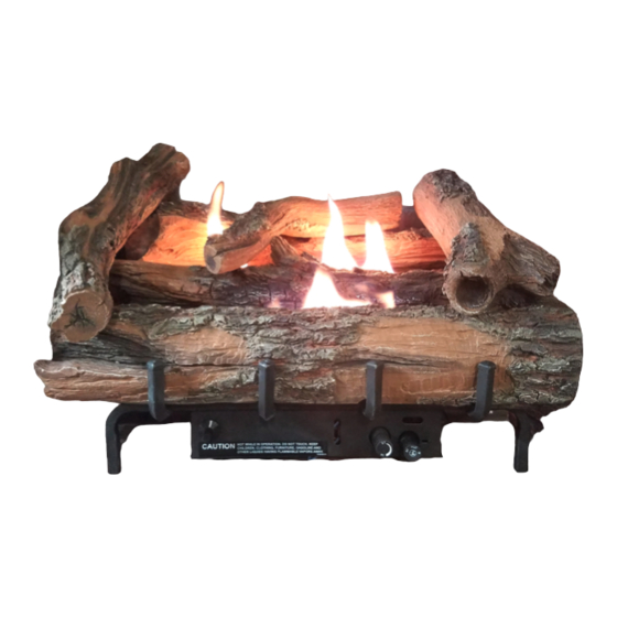
UNVENTED (VENT-FREE) GAS LOG HEATER
OWNER'S OPERATION AND INSTALLATION MANUAL
PFS
REMOTE CONTROL READY BURNER SYSTEM MODELS
FOR USE WITH EWPO18R, EWPO24R, AND EWPO30R LOG SETS
Also Design-Certified As Vented Decorative Appliances
WARNING: If the information in this manual is not
followed exactly, a fire or explosion may result causing
property damage, personal injury or loss of life.
— Do not store or use gasoline or other flammable
vapors and liquids in the vicinity of this or any other
appliance.
— WHAT TO DO IF YOU SMELL GAS
• Do not try to light any appliance.
• Do not touch any electrical switch; do not use any
phone in your building.
• Immediately call your gas supplier from a neighbor's
phone. Follow the gas supplier's instructions.
• If you cannot reach your gas supplier, call the fire
department.
— Installation and service must be performed by a quali-
fied installer, service agency or the gas supplier.
INSTALLER: Leave this manual with the appliance.
CONSUMER: Retain this manual for future reference.
For more information, visit www.cuiheat.com
®
US
EWPO2430NV AND EWPO2430PV
Advertisement
Table of Contents

Related Manuals for Everwarm EWPO2430NV

Summary of Contents for Everwarm EWPO2430NV
- Page 1 UNVENTED (VENT-FREE) GAS LOG HEATER OWNER’S OPERATION AND INSTALLATION MANUAL ® REMOTE CONTROL READY BURNER SYSTEM MODELS EWPO2430NV AND EWPO2430PV FOR USE WITH EWPO18R, EWPO24R, AND EWPO30R LOG SETS Also Design-Certified As Vented Decorative Appliances WARNING: If the information in this manual is not followed exactly, a fire or explosion may result causing property damage, personal injury or loss of life.
-
Page 2: Table Of Contents
TABLE OF CONTENTS Safety ..............2 Cleaning and Maintenance ........ 21 Product Identification ........... 5 Troubleshooting ..........23 Optional Remote Control Accessories ....5 Specifications ............ 27 Unpacking............5 Service Hints ............. 27 Local Codes............5 Technical Service..........27 Product Features ..........5 Replacement Parts .......... - Page 3 SAFETY Continued WARNING: This product con- WARNING: Do not allow fans tains and/or generates chemicals to blow directly into the fireplace. known to the state of California Avoid any drafts that alter burner to cause cancer or birth defects flame patterns. Ceiling fans can or other reproductive harm.
- Page 4 SAFETY Continued 1. This appliance is only for use with the type 9. Before using furniture polish, wax, carpet cleaner or similar products, turn heater off. If of gas indicated on the rating plate. This heated, the vapors from these products may appliance is not convertible for use with create a white powder residue within burner other gases.
-
Page 5: Product Identification
PRODUCT LOCAL CODES IDENTIFICATION Install and use heater with care. Follow all local codes. In the absence of local codes, Piece use the latest edition of The National Fuel Log Set Gas Code, ANSI Z223.1/NFPA 54*. *Available from: American National Standards Institute, Inc. 1430 Broadway New York, NY 10018 National Fire Protection Association, Inc. -
Page 6: Air For Combustion And Ventilation
AIR FOR COMBUSTION AND VENTILATION Unusually tight construction is defined as WARNING: This heater shall construction where: not be installed in a room or space a. walls and ceilings exposed to the out- unless the required volume of side atmosphere have a continuous indoor combustion air is provided water vapor retarder with a rating of one perm (6 x 10... - Page 7 AIR FOR COMBUSTION AND VENTILATION Continued 1. Determine the volume of the space (length B. Vent room directly to the outdoors. See x width x height). Ventilation Air From Outdoors, page 8. Length x Width x Height =__________cu. ft. C. Install a lower Btu/Hr fireplace, if lower Btu/ (volume of space) Hr size makes room unconfined.
-
Page 8: Installation
AIR FOR COMBUSTION AND VENTILATION Continued Ventilation Air From Outdoors Provide extra fresh air by using ventilation Ventilated Outlet Attic grills or ducts. You must provide two perma- nent openings: one within 12" of the ceiling Outlet and one within 12" of the floor. Connect these To Attic items directly to the outdoors or spaces open to the outdoors. - Page 9 INSTALLATION Continued WARNING: Never install the WARNING: Maintain the heater minimum clearances. If you can, • in a bedroom or bathroom provide greater clearances from unless installed as a vented floor, ceiling and adjoining wall. appliance, see page 11 • in a recreational vehicle Carefully follow these instructions.
-
Page 10: Mantel Clearances
INSTALLATION Continued Minimum Noncombustible Material If Using Mantel Clearances If Not Using Mantel You must have noncombustible material(s) Note: If using a mantel proceed to If Using above the fireplace opening. Noncombustible materials (such as slate, marble, tile, etc.) must Mantel. - Page 11 INSTALLATION Continued FLOOR CLEARANCES Determining Minimum Mantel Clearance When Using a Hood The fireplace's required clearances to com- If minimum clearances in Figure 6, page 10, are bustibles must be maintained. Consult your not met, you must have a hood. When using fireplace manufacturer's installation instruc- a hood there are still certain minimum mantel tions for minimum clearances.
- Page 12 INSTALLATION Continued If reasons number 1 or 2 apply to you, WARNING: If installing in a you must permanently open chimney flue damper. You must install the damper clamp sunken fireplace, special care accessory (to order, see Accessories, page is needed. You must raise the 31).
- Page 13 INSTALLATION Continued CAUTION: Never connect Flexible Gas propane/LP fireplace directly Hose (if allowed to the propane/LP supply. This by local codes) heater requires an external regu- Fitting lator (not supplied). Install the external regulator between the heater and propane/LP supply. Figure 10 - Attaching Flexible Gas Hose Installation Items Needed to Heater...
- Page 14 INSTALLATION Continued PROPANE/LP WARNING: Never connect From External Equipment Shutoff Regulator (11" natural gas fireplace to private Valve With 1/8" W.C.** to 14" W.C. NPT Tap* (non-utility) gas wells. This gas Pressure) is commonly known as wellhead NATURAL Approved gas. From Gas Meter Flexible (5"...
- Page 15 INSTALLATION Continued 3. Make sure control knob of heater is in the CAUTION: Make sure exter- OFF position. nal regulator has been installed 4. Check all joints from equipment shutoff between propane/LP supply valve to gas control (see Figures 15 and 16).
- Page 16 INSTALLATION Continued INSTALLING LOGS 3. Place front log onto grate as shown in Figure 18. Front log has cut outs for the WARNING: Failure to position fingers of the grate to fit into. the parts in accordance with these diagrams or failure to use only parts specifically approved with this heater may result in property Front Log...
- Page 17 INSTALLATION Continued Center Top 6. For 24'' and 30'' models: Place the right top log as shown in Figure 22. This log will fit on the matching flat recess on the front, middle, and rear logs. Flat Recess Right Top Flat Recess Flat...
- Page 18 INSTALLATION Continued 8. Final assembly for 18'', 24''and 30'' mod- els is shown in Figures 24, 25 and 26. Figure 26 - Final Assembly For 30'' Models Figure 24 - Final Assembly For 18'' Models Figure 25 - Final Assembly For 24'' Models www.cuiheat.com 126345-01A...
-
Page 19: Operation
OPERATION FOR YOUR SAFETY LIGHTING READ BEFORE LIGHTING INSTRUCTIONS WARNING: If you do not fol- WARNING: low these instructions exactly, • If fireplace has glass doors, a fire or explosion may result never operate this heater with causing property damage, per- glass doors closed. - Page 20 OPERATION Continued 4. Press in and turn control knob clockwise 11. Set flame adjustment knob to any level to the OFF position (see Figure 27). between HI and LO. 5. Wait five (5) minutes to clear out any gas. 12. To leave pilot lit and shut off burners only: Then smell for gas, including near the turn control knob clockwise to the...
-
Page 21: Inspecting Burners
INSPECTING BURNERS Thermocouple Check pilot flame pattern and burner flame Pilot Burner patterns often. PILOT FLAME PATTERN Figure 30 shows a correct pilot flame pattern. Figure 31 shows an incorrect pilot flame pat- Figure 30 - Correct Pilot Flame Pattern tern. - Page 22 CLEANING AND MAINTENANCE Continued 1. Shut off the unit, including the pilot. Allow Ports/Slots the unit to cool for at least thirty minutes. 2. Inspect burner, pilot and primary air inlet holes on Orifice holder for dust and dirt Burner Tube (see Figures 32 and 33).
-
Page 23: Troubleshooting
TROUBLESHOOTING WARNING: Turn off heater and let cool before servicing. Only a qualified service person should service and repair heater. CAUTION: Never use a wire, needle or similar object to clean ODS/pilot. This can damage ODS/pilot unit. Note: All troubleshooting items are listed in order of operation. OBSERVED PROBLEM POSSIBLE CAUSE REMEDY... - Page 24 TROUBLESHOOTING Continued OBSERVED PROBLEM POSSIBLE CAUSE REMEDY ODS/pilot lights but flame 1. Control knob not fully 1. Press in control knob fully goes out when control knob pressed in is released 2. Control knob not pressed in 2. After ODS/pilot lights, keep long enough control knob pressed in 30 seconds...
- Page 25 TROUBLESHOOTING Continued OBSERVED PROBLEM POSSIBLE CAUSE REMEDY Slight smoke or odor during 1. Not enough air 1. Check burner for dirt and initial operation debris. If found, clean burner (see Cleaning and Maintenance, page 21) 2. Residues from manufac- 2. Problem will stop after a few turing processes and logs hours of operation curing...
- Page 26 TROUBLESHOOTING Continued WARNING: If you smell gas • Shut off gas supply. • Do not try to light any appliance. • Do not touch any electrical switch; do not use any phone in your building. • Immediately call your gas supplier from a neighbor’s phone. Fol- low the gas supplier’s instructions.
-
Page 27: Specifications
SPECIFICATIONS EWPO2430PV EWPO2430NV • Rating: 25,000/36,000 Btu/hr • Rating: 25,000/36,000 Btu/hr • Gas Type: Propane/LP • Gas Type: Natural • Ignition: Piezo • Ignition: Piezo • Manifold Pressure: 8.0" w.c. • Manifold Pressure: 3.5" w.c. • Inlet Supply Pressure (inches of water): •... -
Page 28: Parts
PARTS BURNER SYSTEMS EWPO2430NV AND EWPO2430PV www.cuiheat.com 126345-01A... - Page 29 PARTS This list contains replaceable parts used in your heater. When ordering parts, follow the instructions listed under Replacement Parts on page 27 of this manual. NO. PART NO. DESCRIPTION QTY. Log Base • • M11084-26 Screw, HWH AB 10-16 x .38 M12461-26 Screw, HX SLT WSR 10-32 x .38 •...
- Page 30 PARTS EWPO18R, EWPO24R AND EWPO30R LOGS KEY NO. PART NO. DESCRIPTION EWPO18R EWPO24R EWPO30R QTY. 126355-01 Rear Log • 126355-06 Rear Log • 126355-10 Rear Log • 126355-02 Middle Log • 126355-07 Middle Log • 126355-11 Middle Log • 126355-03 Front Log •...
-
Page 31: Accessories
ACCESSORIES NOTICE: All accessories may not be available for all fireplace models. Purchase these accessories from your local dealer. If they can not supply these accessories, call CUI at 1-800-845-5301 for referral informa- tion. You can also write to the address listed on the back page of this manual. -
Page 32: Warranty
WARRANTY KEEP THIS WARRANTY Model (located on product or identification tag) _____________________________ Serial No. (located on product or identification tag) __________________________ Date Purchased __________________________ Keep receipt for warranty verification. CUI LIMITED WARRANTIES New Products Standard Warranty: CUI warrants this new product and any parts thereof to be free from defects in material and workmanship for a period of four (4) years from the date of first purchase from an authorized dealer provided the product has been installed, maintained and operated in accordance with CUI’s warnings and instructions.
Need help?
Do you have a question about the EWPO2430NV and is the answer not in the manual?
Questions and answers