Table of Contents
Advertisement
IMPORTANT SERVICE NOTES (FOR U.S.A. ONLY) ....................................................................................................... 2
SPECIFICATIONS ............................................................................................................................................................. 3
NAMES OF PARTS ........................................................................................................................................................... 4
OPERATION MANUAL ...................................................................................................................................................... 6
QUICK GUIDE (FOR U.S.A. ONLY) .................................................................................................................................. 8
DISASSEMBLY ................................................................................................................................................................ 10
REMOVING AND REINSTALLING THE MAIN PARTS ................................................................................................... 13
ADJUSTMENT ................................................................................................................................................................. 14
NOTES ON SCHEMATIC DIAGRAM .............................................................................................................................. 18
TYPES OF TRANSISTOR AND LED ............................................................................................................................... 18
BLOCK DIAGRAM ........................................................................................................................................................... 19
SCHEMATIC DIAGRAM / WIRING SIDE OF P.W.BOARD ............................................................................................. 22
VOLTAGE ........................................................................................................................................................................ 39
WAVEFORMS OF CD CIRCUIT ...................................................................................................................................... 40
TROUBLESHOOTING ..................................................................................................................................................... 41
FUNCTION TABLE OF IC ................................................................................................................................................ 45
FL DISPLAY ..................................................................................................................................................................... 51
REPLACEMENT PARTS LIST/EXPLODED VIEW
SERVICE MANUAL
MODEL
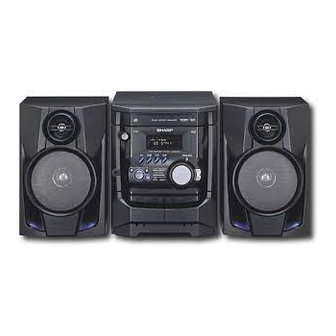
CD-XP200 Mini Component System consisting of CD-XP200
(main unit) and CP-XP200 (speaker system).
MODEL
CD-XP2200 Mini Component System consisting of CD-XP2200
(main unit) and CP-XP2200 (speaker system).
CONTENTS
SHARP CORPORATION
MINI COMPONENT SYSTEM
CD-XP200
MINI COMPONENT SYSTEM
CD-XP2200
• In the interests of user-safety the set should be restored to its
original condition and only parts identical to those specified be
used.
This document has been published to be used
for after sales service only.
The contents are subject to change without notice.
CD-XP200/CD-XP2200
No. S1206CDXP200/
Page
Advertisement
Table of Contents
Troubleshooting

Related Manuals for Sharp CD-XP200


Summary of Contents for Sharp CD-XP200
-
Page 1: Table Of Contents
CD-XP200/CD-XP2200 SERVICE MANUAL No. S1206CDXP200/ MINI COMPONENT SYSTEM CD-XP200 MODEL CD-XP200 Mini Component System consisting of CD-XP200 (main unit) and CP-XP200 (speaker system). MINI COMPONENT SYSTEM CD-XP2200 MODEL CD-XP2200 Mini Component System consisting of CD-XP2200 (main unit) and CP-XP2200 (speaker system). -
Page 2: Important Service Notes (For U.s.a. Only)
CD-XP200/CD-XP2200 IMPORTANT SERVICE NOTES (FOR U.S.A. ONLY) BEFORE RETURNING THE AUDIO PRODUCT (Fire & Shock Hazard) Before returning the audio product to the user, perform the following safety checks. 1. Inspect all lead dress to make certain that leads are not... -
Page 3: Specifications
CD-XP200/CD-XP2200 FOR A COMPLETE DESCRIPTION OF THE OPERATION OF THIS UNIT, PLEASE REFER TO THE OPERATION MANUAL. SPECIFICATIONS CD-XP200/CD-XP2200 Tuner General Frequency range FM: 87.5 - 108 MHz Power source AC 120 V, 60 Hz AM: 530 - 1,720 kHz... -
Page 4: Names Of Parts
CD-XP200/CD-XP2200 NAMES OF PARTS CD-XP200/CD-XP2200 Display 4 5 6 7 1. CD Pause Indicator 2. Extra Bass Indicator 3. Disc Number Indicators 4. Tape 2 Record Indicator 5. FM Stereo Mode Indicator 6. FM Stereo Receiving Indicator 7. Timer Play Indicator 8. -
Page 5: 2. Power On/Stand-By Button
CD-XP200/CD-XP2200 CD-XP200/CD-XP2200 Remote control 1. Remote Control Transmitter 2. Power On/Stand-by Button 3. Disc Number Select Buttons 4. CD Random Button 5. CD Memory Button 6. Tape 2 Record Pause Button 7. CD Track Down or Fast Reverse, Tape 2 Rewind Button 8. -
Page 6: Operation Manual
Cassette deck nician. If something is wrong with this product, check the following before calling your autho- Symptom Possible cause rized SHARP dealer or service center. Is the erase-prevention tab removed? Cannot record. General Cannot record tracks with proper Is it a normal tape? (You cannot record on sound quality. -
Page 7: Remote Control
CD-XP200/CD-XP2200 Remote control Troubleshooting chart Test of the remote control If trouble occurs Point the remote control directly at the remote When this product is subjected to strong external interference (mechanical shock, Remote sensor sensor on the unit. excessive static electricity, abnormal supply voltage due to lightning, etc.) or if it is 8"... -
Page 8: Quick Guide (For U.s.a Only)
CD-XP200/CD-XP2200 QUICK GUIDE (FOR U.S.A ONLY) – 8 –... - Page 9 CD-XP200/CD-XP2200 – 9 –...
-
Page 10: Disassembly
CD-XP200/CD-XP2200 DISASSEMBLY Caution on Disassembly CD-XP200/CD-XP2200 Follow the below-mentioned notes when disassembling Top Cabinet the unit and reassembling it, to keep it safe and ensure Front (A1)x2 excellent performance: Panel ø3x12mm 1. Take cassette tape and compact disc out of the unit. - Page 11 CD-XP200/CD-XP2200 (L1)x3 Loading Tray (E2)x2 (E3)x1 Front Panel (F3)x1 (E2)x1 Headphones (F2)x1 Power PWB Transformer (E4)x1 (L1)x3 Main PWB (F2)x1 (E1)x2 Figure 11-4 ø3x10mm (F1)x2 ø3x10mm (M1)x2 ø3x10mm Figure 11-1 Loading Tray CD Servo (G2)x1 (M3)x2 Front Panel (M2)x1 Display PWB (G1)x12 ø3x10mm...
- Page 12 CD-XP200/CD-XP2200 CP-XP200/CP-XP2200 REMOVAL PROCEDURE FIGURE STEP Woofer 1. Front Panel ..... (A1) x1 12-1 2. Screw ...... (A2) x4 12-2 Tweeter 1. Screw ...... (B1) x2 12-2 (A1)x1 Tweeter (B1)x2 ø3x10mm Screwdriver Speaker Box Driver should Speaker Box Woofer be pried away (A2)x4 from Speaker Box.
-
Page 13: Removing And Reinstalling The Main Parts
CD-XP200/CD-XP2200 REMOVING AND REINSTALLING THE MAIN PARTS TAPE MECHANISM SECTION TAPE 2 Clutch Ass'y Perform steps 1 to 6 and 8 of the disassembly method to remove the tape mechanism. Record/Playback Head How to remove the record/playback and erase heads (TAPE 2) (See Fig. 13-1) 1. -
Page 14: Adjustment
CD-XP200/CD-XP2200 CD MECHANISM SECTION Loading Loading Perform steps 1, 2, 3, 10, 11,12 and 13 of the disassembly Motor PWB Motor method to remove the CD mechanism. Loading Tray How to remove the loading motor (See Fig. 14-1) (A1)x6 1. Bend the hooks (A1) x 6 pcs., to remove the loading motor. - Page 15 CD-XP200/CD-XP2200 TUNER SECTION CD SECTION fL: Low-range frequency • Adjustment fH: High-range frequency Since this CD system incorporates the following automatic • AM IF/RF adjustment functions, readjustment is not needed when replacing the pickup. Therefore, different PWBs and pickups Signal generator: 400 Hz, 30%, AM modulated can be combined freely.
-
Page 16: Test Mode
CD-XP200/CD-XP2200 TEST MODE • Setting the test mode Any one of test mode can be set by pressing several keys as follows. <X-BASS> + <CD> + <POWER> TEST: CD operation test. Function: -CD test mode. -Enter test mode. T E S T IL isn't done OPEN/CLOSE operation is using manual. - Page 17 CD-XP200/CD-XP2200 Standard Specification of Stereo System Error Message Display Contents Error Contents DISPLAY Notes Output while Device Protection Operation. TIMER LED While in Protect Circuit Operate. FLASHING Over Current Detection. DC Detection. TAPE Mechanism Error. 'ER-TA**' 00: Tape Mechanism Error.
-
Page 18: Notes On Schematic Diagram
CD-XP200/CD-XP2200 NOTES ON SCHEMATIC DIAGRAM • Resistor: • The indicated voltage in each section is the one measured To differentiate the units of resistors, such symbol as K and by Digital Multimeter between such a section and the chas- M are used: the symbol K means 1000 ohm and the symbol sis with no signal given. -
Page 19: Block Diagram
CD-XP200/CD-XP2200 DISC CLAMP NUMBER OPEN/ CLOSE T/T UP DOWN LOADING TO MAIN SECTION TO DISPLAY SECTION MOTOR – 9 10 CNP8 CNP7 LC78645NE CD SERVO XOUT 17 25 CONT5 SLDO SPDO VCC4 M63001FP VCC1 FOCUS/TRACKING/ VCC2 SPIN/SLED +3.3V DRIVER VCC3 +3.3V... - Page 20 CD-XP200/CD-XP2200 AM LOOP ANTENNA IC301 ZD351 ANTENNA TA7358AP 5.1V FM FRONT END FM IF 10.7 MHz T302 CF303 BF301 X351 450 kHz CF351 456 kHz B.P.F T351 CF352 CNP301 AM IF FM RF L312 T301 OSC BUFF IC303 Q302 LA1832S AM TRACKING FM IF DET.
- Page 21 CD-XP200/CD-XP2200 FL701 FL DISPLAY TO CD SECTION TAPE MECHANISM Q705 ASS'Y +B10 RX701 52 51 40 25 13 REMOTE SENSOR +B10 +B10 VLOAD AVDD IC701 SW701-SW705 IX0524AW SW711-SW725 SYSTEM MICROCOMPUTER 1 2 4 5 6 7 8 11 12 16 1 7 20 21 22 23 24...
-
Page 22: Schematic Diagram / Wiring Side Of P.w.board
CD-XP200/CD-XP2200 MAIN PWB-A1 (1/3) CD SIGNAL FM SIGNAL VIDEO SIGNAL PLAYBACK SIGNAL C602 RECORD SIGNAL 0.022 R-CH VREF INTERFACE + – Q603, Q604: SYSTEM MUTE R605 C609 A_GND 1/50 LOUT ROUT L-CH R607 C607 CD_GND 3.9K LBASS RBASS R613 D_5V... - Page 23 CD-XP200/CD-XP2200 L-CH C691 R691 R693 6.8K 390P R601 AUX IN C690 R690 6.8K 390P R602 R-CH R692 R603 JK690 C603 VIDEO/AUX 22/50 VREF FACE + – R604 C610 1/50 ROUT C608 RBASS R606 C606 3.9K RTRE C612 0.0022 C614 CHASSIS...
- Page 24 CD-XP200/CD-XP2200 C302 0.001 AM TRACKING AM ANTENNA C331 0.047 C323 0.022 C338 C332 0.001 0.022 T303 D301 C342 DS1SS133 0.022 VD301 AM OSC. SVC348S C335 560P D302 T306 DS1SS133 R336 AM BAND AM LOOP COVERAGE fL ANTENNA BF301 B.P.F IC301...
- Page 25 CD-XP200/CD-XP2200 MAIN PWB-A1 (2/3) TP302 C342 C373 R365 0.015 0.022 C371 R361 R358 1/50 3.9K R350 2.7K C372 R362 1/50 C367 1/50 20 19 18 R352 R355 C357 3.3K 2.2/50 T351 C356 0.001 AM IF R388 TP301 R393 3.9K L352 ZD351 100µH...
- Page 26 CD-XP200/CD-XP2200 IC901 L-CH R-CH STK4029S POWER AMP. +VCC –VCC C908 100P R925 R938 C907 C913 100P 100/63 C905 R943 3.3P R903 (CH) R921 R913 R907 100(1/4W) C916 C915 Fusible 0.1 (1W) 10/63 10/63 R914 R909 0.1 (1W) R923 Q903 R911...
- Page 27 CD-XP200/CD-XP2200 FM SIGNAL C930 47/50 – D912 R949 DS1SS133 FAN MOTOR R947 C931 R950 10/50 R938 R942 R943 R939 CNP705 R945 R944 M_+13.5V 1.5K 1.5K SP_RLY R-CH RL914 L-CH JK701 HEADPHONES HLD803 FW803 HEADPHONES D911 PWB-B2 DS1SS133 C929 0.1(ML) Q905...
- Page 28 CD-XP200/CD-XP2200 DISPLAY PWB-B1 FL701 FL DISPLAY R794 45 44 43 42 41 40 39 38 37 36 35 34 33 32 30 29 28 27 26 25 24 23 22 21 20 19 18 17 16 15 14 13 12...
- Page 29 CD-XP200/CD-XP2200 9 8 7 6 5 4 3 2 1 12 11 10 R795 C701 1/50 93 94 95 96 97 98 99 R763 R702 T-BIAS 0dBATT R703 T_T1/T2 R704 REC/PLAY R705 CD RESOUT R706 SPAN R708 RESET C704 C705...
-
Page 30: Pickup Unit
CD-XP200/CD-XP2200 CD SERVO PWB-C CD SIGNAL 100P(CH 0.022 100P(CH PICKUP UNIT 100P(CH 56P(CH) 100P(CH PICKUP HPC1LX 0.022 VREF VREF 8.2K 1.2K 8.2K 0.047 80 79 78 77 76 75 74 73 72 71 70 69 8.2K EFMIN 0.001 RFVDD 0.0027... - Page 31 CD-XP200/CD-XP2200 100P(CH) 0.022 100P(CH) 100P(CH) 56P(CH) 100P(CH) 0.022 CD RES CLAMP SW 2.2K DISC NO 2.2K 78 77 76 75 74 73 72 71 70 69 68 67 66 65 64 63 62 61 LRCK ASDFIN ASDACK DATA SLCO ASLRCK...
- Page 32 CD-XP200/CD-XP2200 MAIN PWB-A1 C302 R373 X352 R372 R378 R388 R374 R359 1 2 3 4 5 6 7 8 9 C382 10 11 R376 C381 IC302 C387 R360 R379 C397 R377 C392 L351 C394 C385 C391 R381 R395 R375 R382...
- Page 33 CD-XP200/CD-XP2200 P35 12 - D TO DISPLAY PWB CNP701 FFC701 P36 4 - A TO CD SERVO PWB CNP7 1 2 3 4 5 6 7 8 CNS601 COLOR TABLE BROWN C619 R136 C615 Q108 B C E R D ( R )
- Page 34 CD-XP200/CD-XP2200 DISPLAY PWB-B1 RX701 C716 5 6 7 8 9 10 11 12 13 14 15 16 17 18 19 R783 FL701 R793 R792 E C B R763 Q705 R702 C703 D714 D713 R703 R704 R705 Q709 R706 3 2 1...
- Page 35 CD-XP200/CD-XP2200 LED701 SW701 27 28 29 30 31 32 33 34 35 36 37 38 39 40 41 POWER FL701 R792 RD01 C706 IC701 R732 R731 R730 R762 R729 30 31 R736 R718 R768 C720 R766 CNP701 R767 FFC701 SW711...
- Page 36 CD-XP200/CD-XP2200 P34 1 - D P33 9 - B FROM DISPLAY PWB FROM MAIN PWB CNS701 CNS601 CD SERVO PWB-C CNP7 1 2 3 4 5 6 7 8 9 10 1 2 3 4 5 6 7 8 CNP8...
- Page 37 CD-XP200/CD-XP2200 P34 3 - G TAPE MECHANISM TO DISPLAY PWB ASSEMBLY CNP702 FFC702 TAPE MECHANISM PWB-F SOLENOID SOLENOID TAPE MOTOR TAPE 2 TAPE 1 RECORD/PLAYBACK PLAYBACK HEAD ERASE HEAD HEAD CD LOADING MOTOR PWB-E OPEN/CLOSE T/T UP/DOWN LOADING MOTOR 7 6 5 4 3 2 1...
- Page 38 CD-XP200/CD-XP2200 AC POWER SUPPLY CORD AC 120 V, 60 Hz TRANSFORMER PWB-A3 COLOR TABLE BROWN R D ( R ) ORANGE YELLOW GREEN BLUE VIOLET GRAY W H ( W ) WHITE BLACK PINK T.F. POWER PWB-A2 F804 2A/125V C805...
-
Page 39: Voltage
CD-XP200/CD-XP2200 VOLTAGE IC301 IC601 1C701 IC851 VOLTAGE VOLTAGE VOLTAGE VOLTAGE VOLTAGE VOLTAGE VOLTAGE 1.59 V 1.65 V 4.78 V 4.79 V 20.80 V 1.04 V 1.65 V 4.70 V 1.32 V 1.59 V 1.86 V 13.40 V 1.77 V 2.12 V 4.42 V... -
Page 40: Waveforms Of Cd Circuit
CD-XP200/CD-XP2200 WAVEFORMS OF CD CIRCUIT Stopped Stopped 1999/04/07 09:51:15 CH1=500 mV CH3=500 mV CH1=200 mV CH2=500 mV 500 ms/div 500 ms/div DC 10:1 DC 10:1 (500 ms/div) DC 10:1 DC 10:1 (500 ms/div) NORM:20 kS/s NORM:20 kS/s IC1 21 IC1 21... -
Page 41: Troubleshooting
CD-XP200/CD-XP2200 TROUBLESHOOTING When the CD does not function When the CD section does not operate when the objective lens of the optical pickup is dirty, this section may not operate. Clean the objective lens, and check the playback operation. When this section does not operate even after the above step is taken, check the following items. - Page 42 CD-XP200/CD-XP2200 Stopped (1) Focus-HF system check. CH1=500 mV CH3=500 mV 500 ms/div DC 10:1 DC 10:1 (500 ms/div) NORM:20 kS/s Although a CD is inserted and the cover is closed, "NO DISC" is displayed. Press the OPEN/CLOSE switch (SW1) without inserting a disc, and try starting the playback operation.
- Page 43 CD-XP200/CD-XP2200 (2) Tracking system check. Check the TE waveform at pin 15 on IC1. The tracking servo is not activated. If the waveform shown in Figure 43-1 appears and soon after Check the peripheral circuits at pins 14, 15 and 20 on IC1, and NO DISC appears ? CNS1A/B.
- Page 44 CD-XP200/CD-XP2200 (4) PLL system check. Stopped 1999/04/05 17:33:17 CH1=500 mV CH3=1 V CH4=1 V 500 ms/div DC 10:1 DC 10:1 DC 10:1 (500 ms/div) NORM:20 kS/s When a disc is loaded, start play operation. PDO1 The HF waveform is normal, but the TOC data cannot be PDO2 read.
-
Page 45: Function Table Of Ic
CD-XP200/CD-XP2200 FUNCTION TABLE OF IC IC1 VHiLC78645NE1: CD Servo (LC78645NE) (1/2) Terminal Name Input/Output Setting in Reset Pin No. Function SLCO Output — Control output. For slice level SLCIST Input — Resistor connection terminal for SLCO output current setting. control. - Page 46 CD-XP200/CD-XP2200 IC1 VHiLC78645NE1: CD Servo (LC78645NE) (2/2) Terminal Name Input/Output Setting in Reset Function Pin No. RVSS — — GND for Right channel. Must be connected to 0 V. Right channel RCHO Output LVDD /2 Right channel output. D/A converter...
- Page 47 CD-XP200/CD-XP2200 IC1 VHiLC78645NE1: CD Servo (LC78645NE) 75 74 72 71 69 68 66 65 63 62 SLCO DATA SLCIST EFMIN LRCK ASDFIN RFVDD ASDACK RFVSS ASLRCK FIN1 16MOUT FIN2 EFLG TIN1 TIN2 XVSS LC78645NE VREF FSX/16MIN REF1 XOUT XVDD RVDD...
- Page 48 CD-XP200/CD-XP2200 IC601 VHiLC75341/-1: Audio Processor (LC75341) ROUT LOUT LBASS RBASS LTRE RTRE LSEL0 RSEL0 R1 R2 24 23 22 21 20 19 18 17 16 15 14 13 LC75341 10 11 12 Figure 48 BLOCK DIAGRAM OF IC – 48 –...
- Page 49 CD-XP200/CD-XP2200 IC701 RH-iX0524AWZZ: System Microcomputer (IX0524AW) (1/2) Pin No. Port Name Terminal Name Input/Output Function Input (+) Power supply. -20dBATT Output -20dB Attenuator. NO USE Output Open T_BIAS Output Tape record bias. T_T1/T2 Output Tape T1/T2 change. T_REC/PLY Output Tape REC/PLAY change.
- Page 50 CD-XP200/CD-XP2200 IC701 RH-iX0524AWZZ: System Microcomputer (IX0524AW) (2/2) Pin No. Port Name Terminal Name Input/Output Function P120 O/C SW Input CD OPEN/CLOSE SW. P117 MIC SW Input Mic switch input. P116 KARA_LATCH Output Karaoke latch. (When not used. Connect to 0 V.)
-
Page 51: Fl Display
CD-XP200/CD-XP2200 FL DISPLAY FL701 VVKNA09SS29-1 GRID ASSIGNMENT X-BASS REC ST SLEEP TP TI PTYIPTY MHz TA MEMORY h j k (1G~8G) ANODE CONNECTION X-BASS PTYI MEMORY PRO LOGIC SLEEP – 51 –... - Page 52 CD-XP200/CD-XP2200 — M E M O — – 52 –...
- Page 53 CD-XP200/CD-XP2200 PARTS GUIDE MINI COMPONENT SYSTEM CD-XP200 MODEL CD-XP200 Mini Component System consisting of CD-XP200 (main unit) and CP-XP200 (speaker system). MINI COMPONENT SYSTEM CD-XP2200 MODEL CD-XP2200 Mini Component System consisting of CD-XP2200 (main unit) and CP-XP2200 (speaker system). “HOW TO ORDER REPLACEMENT PARTS”...
- Page 54 CD-XP200/CD-XP2200 PRICE PRICE DESCRIPTION PARTS CODE DESCRIPTION PART CODE RANK RANK T351 RCILI0019AWZZ AD AM IF CD-XP200/CD-XP2200 COILS INTEGRATED CIRCUITS AC 0.82 µH,Choke VP-XHR82K0000 VHILC78645NE1 AY CD Servo,LC78645NE AB 330 µH,Choke L103 VP-MK331K0000 VHIM63001FP-1 AX Focus/Tracking/Spin/Sled Driver, L312 RCILR0056AWZZ AB FM RF M63001FP AB 100 µH,Choke...
- Page 55 CD-XP200/CD-XP2200 PRICE PRICE DESCRIPTION PART CODE PARTS CODE DESCRIPTION RANK RANK AB 22 µF,50V,Electrolytic AA 0.0022 µF,16V C133 VCEAZA1HW226M J C625,626 VCTYMN1CX222K J AC 220 µF,10V,Electrolytic AA 0.001 µF,50V C134 VCEAZA1AW227M J C635~638 VCKYMN1HB102K J AA 0.022 µF,25V AB 1 µF,50V,Electrolytic...
- Page 56 CD-XP200/CD-XP2200 PRICE PRICE DESCRIPTION PARTS CODE DESCRIPTION PART CODE RANK RANK VRD-ST2EE1R0J AA 1 ohm,1/4W R612,613 VRD-MN2BD391J AA 390 ohms,1/8W 1 R51 VRG-ST2EG3R3J AB 3.3 ohms,1/4W,Fusible R614,615 VRD-MN2BD472J AA 4.7 kohms,1/8W R101,102 VRD-MN2BD102J AA 1 kohm,1/8W R616 VRD-MN2BD222J AA 2.2 kohms,1/8W...
- Page 57 CNP101 QCNCM705CAFZZ J AA Plug,3Pin CABINET PARTS CNP102 QCNCM705GAFZZ J AB Plug,7Pin CNP301 92LCONE3P5268 AC Plug,3Pin 92LCAB4233AASY J Front Panel Ass’y [CD-XP200] CNP601 QCNCWZX19AWZZ J AD Socket,19Pin 92LCAB4236AASY J Front Panel Ass’y [CD-XP2200] CNP701 QCNCWZF19AWZZ J Plug,19Pin 201- 1 ————...
- Page 58 203- 2 PCUSG0022AWZZ J AB Cushion,Leg XEBSD30P12000 AA Screw,ø3×12mm GCAB-1197AWZZ AM Loading Tray XESSD30P10000 AA Screw,ø3×10mm GCAB-1215AWSA AT Top Cabinet [CD-XP200] XHBSD26P04000 AA Screw,ø2.6×4mm GCAB-1215AWSB Top Cabinet [CD-XP2200] XHBSD40P08000 AA Screw,ø4×8mm GCOVA1416AWSA J AL Cover,CD Tray [CD-XP200] XJBSD20P05000 AA Screw,ø2×5mm...
- Page 59 CD-XP200/CD-XP2200 PRICE DESCRIPTION PART CODE RANK CP-XP200/CP-XP2200 SPEAKER BOX PARTS GBOXS0088AWSA J Speaker Box Ass’y [CP-XP200] GBOXS0088AWSC J Speaker Box Ass’y [CP-XP2200] CPNLS1056AW01 Front Panel Ass’y [CP-XP200] CPNLS1056AW02 Front Panel Ass’y [CP-XP2200] QCNWN1833AWZZ J AH Speaker Cord Ass’y (with Capacitor C1,2)
- Page 60 CD-XP200/CD-XP2200 CD-XP200/CD-XP2200 306-2 306-1 306-3 703x2 305x2 PWB-D Figure 7 CD MECHANISM EXPLODED VIEW – 7 –...
- Page 61 CD-XP200/CD-XP2200 CD-XP200/CD-XP2200 BELT CONNECTION 202-1 FF/REW Tape FF/REW 614x3 ROLLER Motor ROLLER PWB-A1 ASS'Y ASS'Y IC851 614x2 IC852 IC853 FLYWHEEL FLYWHEEL ASS'Y ASS'Y MAIN BELT TAPE 2 TAPE 1 Silicon Silicon Grease 614x2 614x10 Grease IC901 202-2 610x5 230 611x2...
- Page 62 CD-XP200/CD-XP2200 CD-XP200/CD-XP2200 609x2 MECHANISM 609x2 PWB-E 619x2 PWB-C Figure 9 CABINET EXPLODED VIEW (2/2) – 9 –...
- Page 63 CD-XP200/CD-XP2200 CP-XP200/CP-XP2200 SP3, 4 TWEETER SP3, 4 C1, 2 TWEETER Capacitor 2.7µF, 100V(N.P.) – C1, 2 Capacitor SP1, 2 2.7µF, 100V(N.P.) WOOFER – SP1, 2 WOOFER SP3, 4 907x2 904x2 SP1, 2 C1, 2 908x4 904x2 Figure 10 SPEAKER EXPLODED VIEW...
-
Page 64: Packing Of The Set (For U.s.a. Only)
SPAKC1416AWZZ [CD-XP2200] Packing Case SPAKZ0887AWZZ Not Replacement Item Pad, Bottom © COPYRIGHT 2002 BY SHARP CORPORATION SHARP CORPORATION ALL RIGHTS RESERVED. AV Systems Group Audio Systems Division No part of this publication may be reproduced, Higashihiroshima, Hiroshima 739-0192, Japan stored in a retrieval system, or transmitted in...
Need help?
Do you have a question about the CD-XP200 and is the answer not in the manual?
Questions and answers